A 0.05 mm burr on a stamped electrical terminal passes the press-side dimensional check but fails at the connector assembly station 500 insertion cycles later. The burr ridge transfers to the mating contact surface and drives contact resistance from 5 mΩ to 20 mΩ — a failure invisible on the incoming inspection report.
In this analysis, you will learn systematic burr diagnosis across three variable categories — material temper and alloy behavior, progressive die tooling geometry, and press process parameters — with corrective action sequences ordered from least invasive to tooling-level intervention and CMM-based verification protocol.
Read on for the full root cause analysis.
Burr Identification
A burr on stamped electrical terminals presents as a raised ridge along the punch-exit edge of the sheared profile. Under 20x magnification, three burr morphologies distinguish the underlying failure mechanism: a continuous thin ribbon below 0.02 mm indicates normal shear within acceptable clearance, a jagged torn lip between 0.03 mm and 0.08 mm points to excessive die clearance or worn punch edges, and a folded-over flap above 0.08 mm signals severe clearance drift combined with inadequate stripper pressure.
The burr forms because the material between the punch and die does not fracture cleanly at the intended shear plane. Instead, a portion of the strip cross-section flows plastically into the clearance gap before crack propagation separates the part from the carrier strip. The height of the residual ridge is a direct function of clearance-to-thickness ratio, material yield strength, and the radius condition of the cutting edges.
Measurement Positions
Measure burr height at three positions per terminal edge — the lead-in corner, the mid-point of the straight section, and the exit corner. Localized clearance variation from uneven punch-to-die alignment produces burr height differences of 0.01 mm to 0.03 mm across these three positions on the same terminal edge.
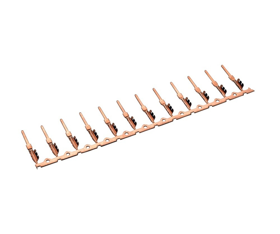
A consistent burr height across all three positions indicates uniform clearance that has drifted as a global parameter. A burr spike at only the exit corner suggests a punch deflection issue. The punch tip bends under cutting force and widens clearance asymmetrically at the trailing edge of the cut stroke.
Root Cause Categories
Material Variables
Coil-to-coil variation in temper within the same alloy grade is the material variable most frequently overlooked during burr troubleshooting. A C26000 brass strip certified as half-hard with a tensile strength of 420 MPa produces burrs under 0.02 mm at 12% clearance. The same die running a coil at the upper bound of the half-hard range at 490 MPa tensile strength generates burrs 0.04 mm or higher at identical clearance because the higher yield strength delays fracture initiation by 15–20% of the punch penetration depth.
Grain size distribution in copper alloy strip also drives burr variability. Fine-grain material with ASTM grain size 6–8 shears cleanly with a burnish zone occupying 35–40% of the cut edge. Coarse-grain material at ASTM grain size 3–4 produces a rough fracture surface with intermittent burr spikes because the crack path follows grain boundaries rather than the intended shear plane.
Work-hardened tempers compound the clearance sensitivity. C17200 beryllium copper at full-hard temper with 1,200 MPa tensile strength demands 8–10% clearance per side. Running the standard 10–12% clearance window on this alloy produces burrs double the height measured on C26000 because the material resists shear localization and extrudes into the die gap as a continuous raised ridge.
Tooling Deficiencies
Punch edge radius is the dominant tooling variable. A fresh carbide punch enters production with an edge radius under 0.005 mm and cuts by initiating a shear band at the punch-tip contact line. After 250,000 strokes, the edge radius wears to 0.025 mm. At this threshold, the cutting mechanism shifts from shear-dominant to a mixed shear-extrusion mode that produces burr heights 0.01 mm to 0.02 mm above the baseline.
At 500,000 strokes with an edge radius exceeding 0.05 mm, the punch no longer initiates fracture at the contact line. The rounded edge extrudes material into the die gap before sufficient pressure builds to trigger crack propagation, producing burrs 0.03 mm to 0.05 mm above the fresh-tool baseline. This is the inflection point where most production runs first detect burr-related quality rejects.
Die land wear introduces a secondary effect. A worn die land with a radius exceeding 0.02 mm at the cutting edge reduces the effective clearance by creating a radius-entry zone that redirects material flow downward rather than laterally into the clearance gap. The burr morphology shifts from a sharp raised ridge to a rounded hump that passes visual inspection but measures above the 0.03 mm threshold on a profilometer.
Process Parameters
Stripper pressure below 10% of the press tonnage rating is the process variable most directly correlated with burr escalation. The stripper plate must clamp the strip against the die face with sufficient force to prevent material lift during punch retraction. When stripper pressure drops below this threshold, the strip lifts 0.005 mm to 0.010 mm off the die face, the effective clearance widens asymmetrically, and burr height increases 0.01 mm to 0.03 mm per stroke until the condition is corrected.
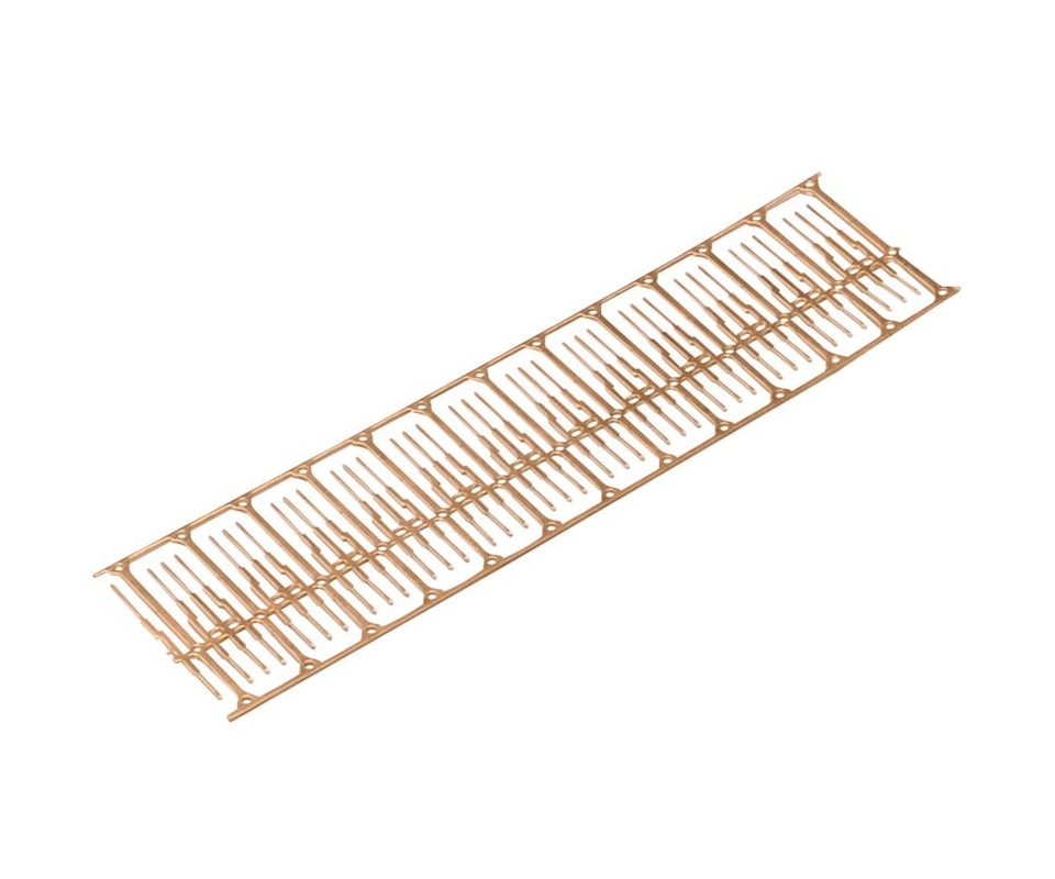
Press ram deflection under load is a less visible but equally destructive process variable. A 400-ton press under 60–70% rated tonnage deflects the ram by 0.02 mm to 0.05 mm at the center of the die set compared to the outer stations. Stations positioned near the die center run at wider effective clearance than outer stations, producing burr height variation of 0.01 mm to 0.04 mm across a single terminal strip — a pattern that dimensional inspection at only one station misses entirely.
Lubrication starvation at high stroke rates compounds all other process variables. At 800 SPM and above, the oil film between punch and strip thins to below 0.5 µm, adhesive wear accelerates, and the punch edge radius increases at roughly 3x the rate observed at 400 SPM. Burr height escalation follows the edge wear curve with a 20,000-stroke lag before detection.
Deep Dive: Explore process capability studies for progressive die tooling — including Cpk trend analysis, punch wear rate curves, and die-life projection models — to establish predictive maintenance intervals before burr height exceeds the PPAP threshold.
💡 Die Clearance Audit: Kravzik’s tooling engineers can audit your current die set against industry-standard clearance benchmarks for your specific alloy and temper, and return a die-life projection with recommended re-grind intervals. Request a die clearance audit with your current burr measurement data.
Parameter Adjustments
Non-Destructive Adjustments
These adjustments are reversible and can be executed without removing the die set from the press. Execute them in sequence, measuring burr height after each change to isolate the effective variable.
- Verify stripper pressure at 12–15% of press tonnage rating. Increase pressure by 5% increments until strip lift during punch retraction is eliminated. Measure with a dial indicator mounted on the stripper plate at the station producing the highest burr.
- Reduce stroke rate by 100 SPM increments. Measure burr height after 1,000 strokes at each speed. If burr height drops at lower SPM, lubrication film thickness is the limiting factor. Increase oil delivery volume by 20% at the high-SPM setting and re-test.
- Check coil set and strip flatness entering the first station. A coil curvature exceeding 0.5 mm per 100 mm of strip length causes the strip to enter the die at a compound angle, shifting the effective punch-to-die alignment at the lead-in corner by 0.01 mm or more. Install a straightener if coil set exceeds this threshold.
- Verify punch-to-die alignment across all stations using shim stock or lead wire impression. Stations with clearance variation exceeding 0.005 mm from the nominal value require re-alignment. Concentrate measurement on the stations producing the highest burr heights.
Destructive and Tooling Adjustments
These adjustments require die removal from the press and toolroom intervention. Execute only after non-destructive adjustments fail to reduce burr height below the 0.03 mm threshold.
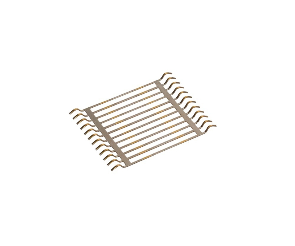
- Re-grind punch faces to restore edge radius below 0.005 mm. Remove 0.05 mm to 0.10 mm from the punch face — enough to eliminate the worn radius zone without altering the punch length beyond the die design tolerance. Re-grind all punches in the set simultaneously to maintain uniform clearances.
- Sharpen die land cutting edges if the land radius exceeds 0.02 mm. A die land with visible rounding under 10x magnification is overdue for sharpening. The sharpening cut removes 0.03 mm to 0.05 mm from the die land surface and restores the clean 90-degree edge required for shear initiation.
- Replace worn punches at stations where the edge radius exceeds 0.05 mm or the punch length has been ground below the minimum design dimension. Installing a fresh carbide punch at a single station without replacing adjacent punches can introduce clearance asymmetry if the new punch has a different overall length due to grinding history.
- Execute complete die re-grind when multiple stations show simultaneous burr escalation. This requires full disassembly and inspection of every punch and die insert for fatigue cracking, chipping, or asymmetric wear patterns.
For die sets approaching the end of their service life with cumulative grinding losses exceeding 1.5 mm from the original punch length, replacement of the full punch-and-die set is more cost-effective than incremental re-grinding. Contact progressive die tooling maintenance services for a re-grind assessment when burr height trends upward across three consecutive maintenance intervals.
Verification Protocol
CMM Measurement Protocol
Burr height verification after corrective action requires a coordinate measuring machine set to a 20-point grid across the terminal profile, following quality assurance inspection protocols. Each measurement point must include the burr height at the punch-exit edge, the material thickness at the same location, and the perpendicularity deviation of the sheared edge relative to the terminal surface plane.
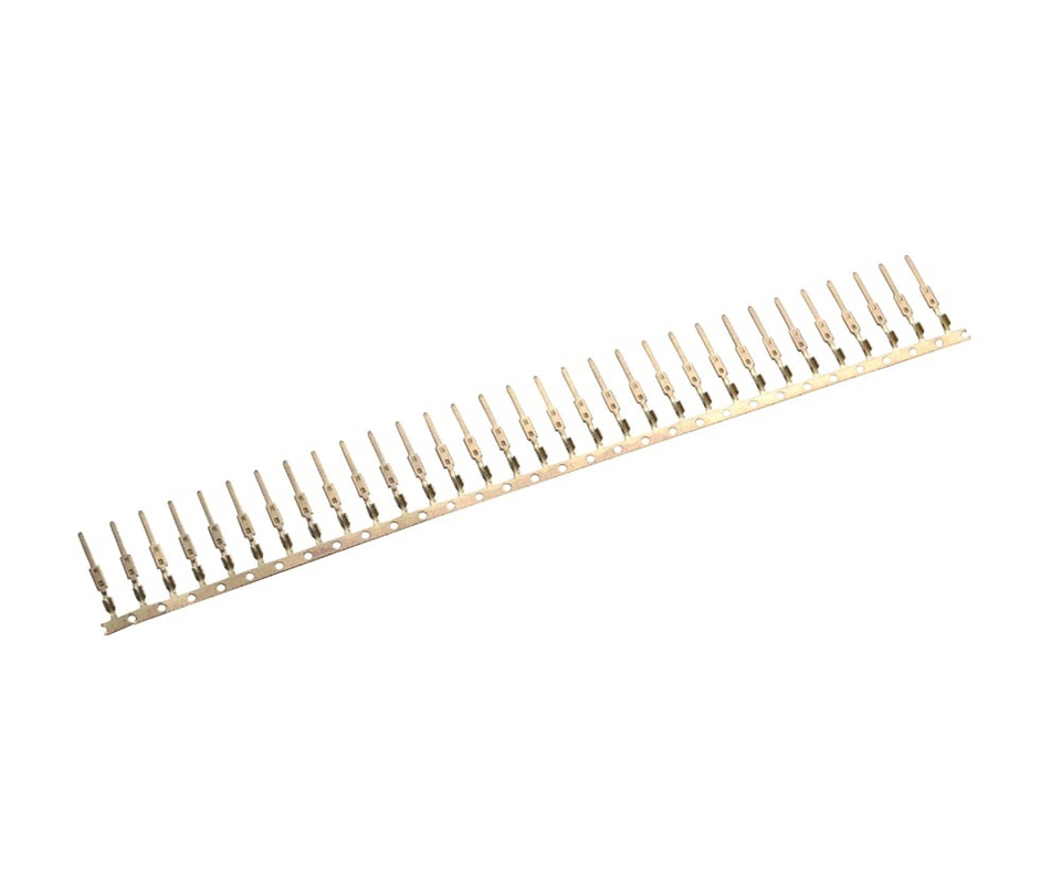
Sample size for post-adjustment verification is 30 pieces drawn from three coil positions — the first 5 meters, the mid-coil point, and the last 5 meters. This sampling pattern captures any temper variation within the coil that could mask the effectiveness of the corrective action. Calculate Cpk from the 30-point dataset with a target burr height of 0.025 mm and an upper specification limit of 0.03 mm.
A Cpk value of 1.33 or higher across all three coil positions confirms that the corrective action restored process capability with adequate margin. A Cpk below 1.33 at the mid-coil position despite acceptable values at the coil ends indicates a temper transition zone within the coil. Flag the coil supplier and request mill certificates for the affected heat numbers.
Functional Validation
Dimensional verification must be supplemented with functional testing because burrs that pass the 0.03 mm height threshold can still cause connector assembly failures if the burr morphology creates a sharp ridge profile rather than a rounded hump. The ridge profile concentrates insertion force on a narrow contact area and gouges the mating connector surface during the first insertion cycle.
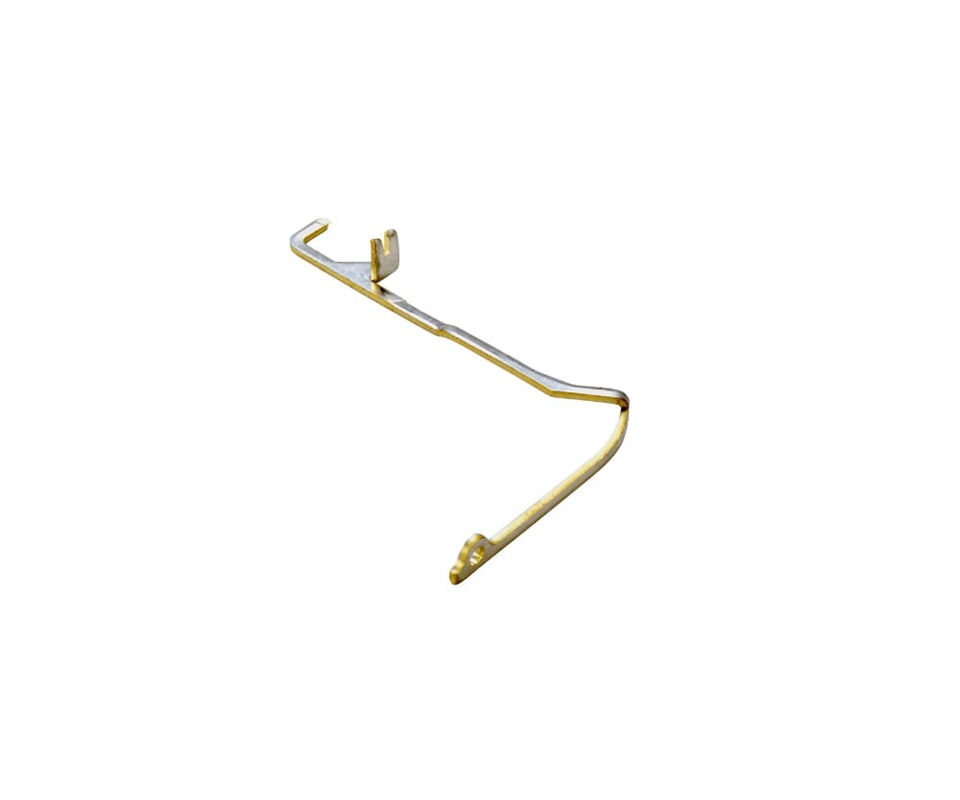
Execute a 30-cycle insertion-and-extraction test on 10 terminals from the verified batch. Measure contact resistance at insertion cycles 1, 10, and 30 using a four-wire Kelvin measurement at 100 mA test current. A contact resistance shift exceeding 2 mΩ between cycle 1 and cycle 30 indicates burr-induced surface damage on the mating contact. The burr is mechanically compliant with the height specification but functionally unacceptable.
💡 Burr Diagnostic Review: Kravzik’s quality engineering team performs burr root cause analysis on production terminals using CMM profiling, SEM cross-section imaging, and insertion-cycle contact resistance testing to isolate the material, tooling, or process variable driving burr escalation. Send your burr measurement data for a diagnostic report with corrective action recommendations.
Fix & Verify
Adjusting die clearance to fix burr without verifying the effect on edge cracking across heat numbers trades one failure mode for another. Kravzik’s in-house toolroom performs data-driven punch re-grinds with post-service CMM verification, tracking clearance, edge radius, and burr height across all stations before the die returns to production.
Send your terminal drawing for a complete burr root cause analysis with Cpk capability study and re-grind interval recommendations, delivered within 48 hours.