A stamped electrical terminal passes insertion force and contact resistance testing at final inspection, then enters service in an engine-compartment connector. After 800 thermal cycles between −40°C and 125°C, the contact force decays from 1.5 N to 0.8 N and contact resistance climbs from 5 mΩ to 25 mΩ — an intermittent open circuit that triggers a warranty claim for the entire wiring harness assembly.
In this analysis, you will learn how to diagnose spring force relaxation across three root cause categories — alloy selection and temper, forming strain and bend geometry, and operating temperature ceiling — with corrective design parameter adjustments ranked from material substitution to geometry redesign, verified through USCAR-2 force-deflection testing.
Read on for the full root cause analysis.
Relaxation Symptom
Spring force relaxation in stamped electrical terminals manifests as a gradual decline in the normal force that the terminal contact beam exerts against the mating pin. The terminal initially meets the 1.0 N minimum contact force specified by USCAR-2 at assembly. After thermal cycling or sustained elevated temperature, the force drops below the threshold without any visible deformation or dimensional change — the terminal looks identical to a passing part under visual inspection.
The failure presents in the field as intermittent high resistance rather than a hard open circuit. The connector passes a wiggle test because mechanical vibration momentarily restores contact, but resistance spikes reappear within minutes. This pattern mimics a pin fretting corrosion failure and is misdiagnosed in approximately 60% of field return analyses because the terminal geometry measures within print at room temperature.
Force-Deflection Measurement
Measure the contact beam force at three deflection points — 0.5 mm, 1.0 mm, and 1.5 mm from the free position — using a force gauge with 0.01 N resolution mounted on a micrometer-driven stage. A terminal that delivers 1.5 N at the nominal 1.0 mm deflection point but only 0.4 N at 0.5 mm indicates the relaxation is concentrated in the low-deflection region where the beam operates near its elastic limit.
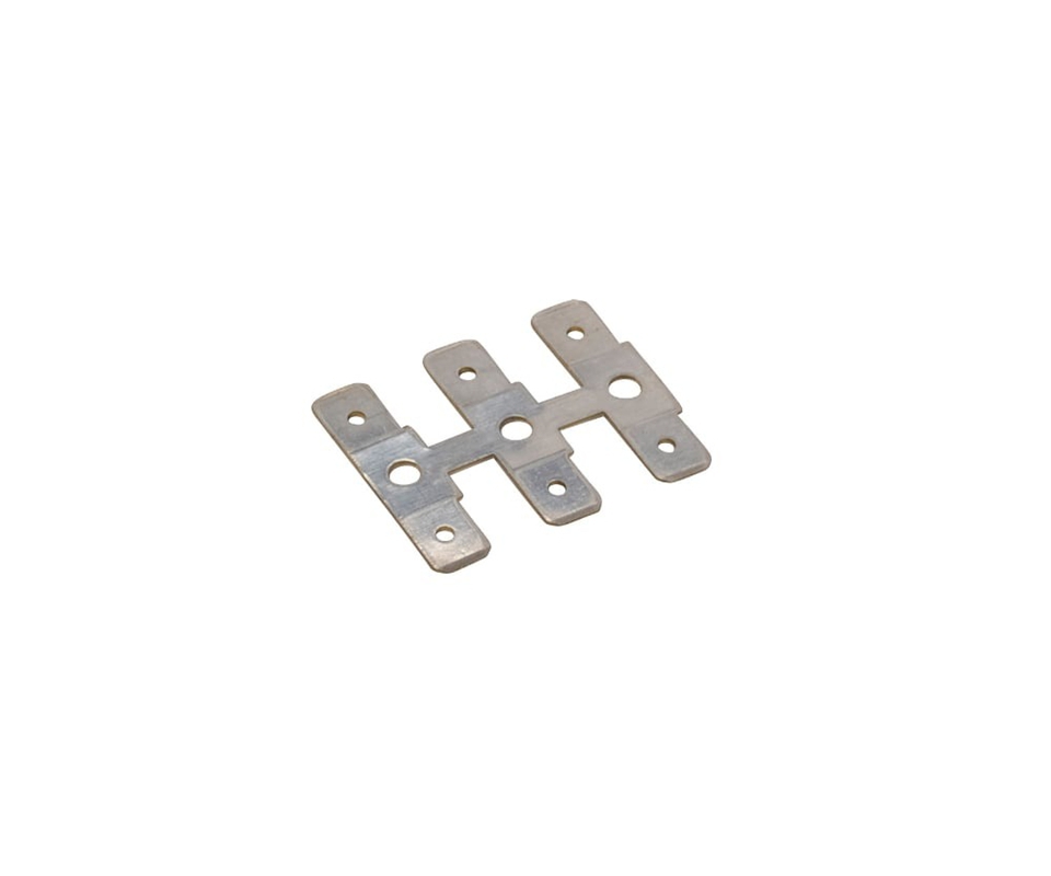
Compare the force-deflection curve of a field-returned terminal against a retained production sample from the same lot. A parallel downward shift across all three deflection points indicates uniform stress relaxation throughout the beam cross-section. A steeper drop at the 0.5 mm point alone indicates localized relaxation at the beam root where forming strain is highest.
Root Cause Categories
Alloy Selection
The dominant material variable in contact force relaxation is the alloy’s stress relaxation resistance at the service temperature. Stress relaxation is a thermally activated process — atoms in the crystal lattice rearrange under sustained elastic strain to reduce internal stress, and the rate of rearrangement doubles for approximately every 15°C increase above the alloy’s relaxation threshold temperature.
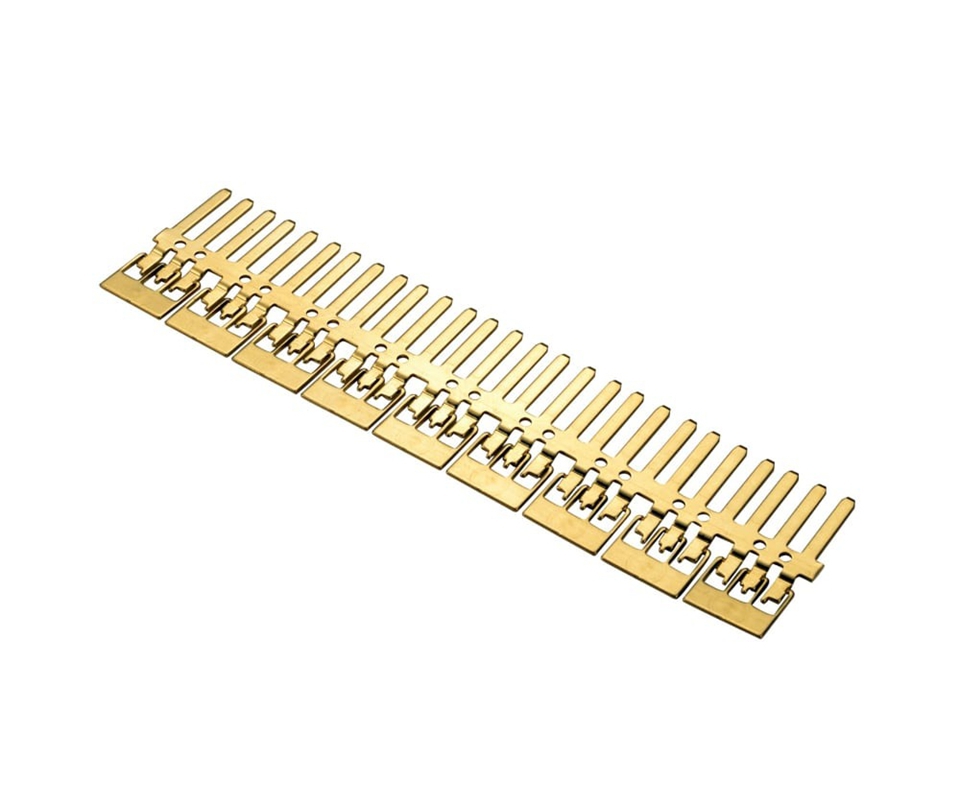
C26000 cartridge brass begins measurable stress relaxation at 65°C, losing 10% of initial stress within 100 hours at this temperature. At 85°C — a common engine-compartment ambient — C26000 loses 40% of initial contact force within 1,000 hours.
C51000 phosphor bronze raises the relaxation threshold to 85°C and retains 85% of initial force after 1,000 hours at 105°C. C17200 beryllium copper in mill-hardened temper operates reliably to 150°C with less than 8% force loss over 1,000 hours.
Alloy substitution from C51000 to C17200 is the most effective single corrective action for terminals operating above 85°C. The cost increase — typically 3× to 5× the raw material cost — is offset by the elimination of intermittent field failures. For applications with a maximum ambient of 75°C, copper alloy strip in C51000 half-hard temper provides adequate relaxation resistance without the beryllium copper cost premium.
Forming Strain
The bend radius at the contact beam root is the forming parameter with the strongest correlation to relaxation rate. A bend radius of 0.5× material thickness — achievable with coining tooling — produces a strain-hardened zone at the inner bend surface where residual tensile stress exceeds 60% of the alloy’s yield strength. This residual stress drives accelerated relaxation because the stored elastic energy provides the activation energy for atomic rearrangement at lower temperatures.
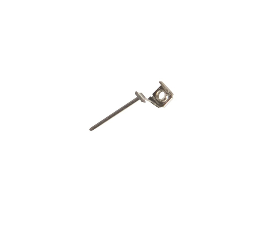
Increasing the bend radius to 2.0× material thickness reduces the residual stress at the inner bend surface to approximately 25% of yield strength. Terminals formed with 2.0× radii retain 92% of initial contact force after 1,000 hours at 105°C, compared to 78% retention for identical alloy and temper at 0.5× radius. The trade-off is a proportional reduction in the spring rate — the terminal deflects more per unit force — which may require a longer beam length to achieve the target insertion force window.
Coining at the bend apex introduces a compressive residual stress layer that counteracts the tensile stress from bending. A coining depth of 10% of material thickness at the bend apex reduces the net residual stress by 30% to 40% and extends the relaxation life by approximately 2× at the same temperature. This technique is particularly effective on C51000 terminals where alloy substitution to C17200 is cost-prohibitive.
Operating Temperature
Temperature accelerates stress relaxation exponentially, not linearly. A terminal rated for 5,000 hours at 85°C may fail in under 200 hours at 125°C because the relaxation rate follows an Arrhenius relationship with an activation energy of 0.8 eV to 1.2 eV for copper alloys. A 40°C temperature increase reduces the time to 20% force loss by a factor of 20 to 50, not by a factor of 2 to 3 as a linear extrapolation would predict.
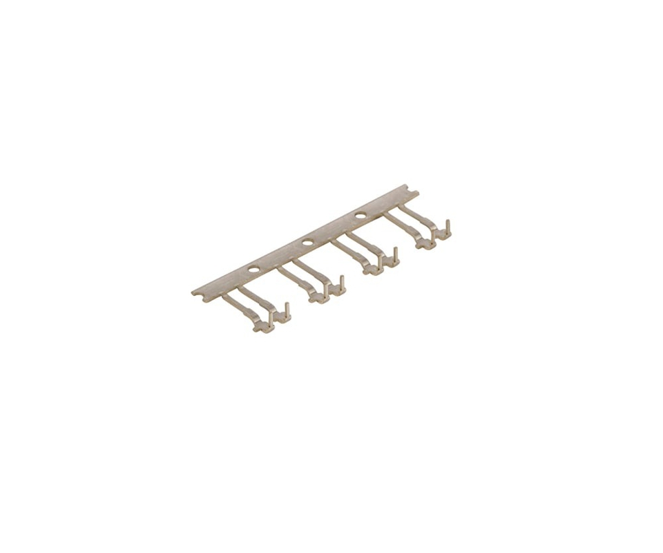
Connector housing material contributes a secondary temperature effect. A PBT housing with a 150°C heat deflection temperature appears adequate for a 125°C terminal rating, but the housing softens sufficiently at 120°C to allow 0.05 mm to 0.10 mm of terminal movement within the cavity. This movement shifts the contact beam to a different deflection point on its force-deflection curve, compounding the material relaxation effect.
Deep Dive: Explore stress relaxation testing per ASTM E328 — including isothermal hold testing at three temperatures, Larson-Miller parameter extrapolation, and residual stress measurement by X-ray diffraction — to predict terminal contact force retention over the full vehicle lifecycle.
Alloy Stress Relaxation Audit: Kravzik’s material engineering team evaluates your terminal alloy selection against the operating temperature profile extracted from the connector specification, and returns a relaxation life projection with alloy substitution recommendations where the current selection falls below the 85% force retention threshold. Send your terminal drawing for a stress relaxation audit with alloy comparison data.
Design Adjustments
Non-Destructive Adjustments
These adjustments modify the terminal design within the existing connector cavity envelope and do not require tooling changes to the progressive die beyond punch profile modifications.
- Increase contact beam bend radius to 2.0× material thickness minimum. This reduces residual tensile stress at the bend root and extends relaxation life by 2× to 3× at the same alloy and temperature. Verify that the larger radius does not increase the beam envelope beyond the connector cavity clearance.
- Apply coining at the bend apex to a depth of 8% to 12% of material thickness. The compressive stress layer offsets tensile bending stress and reduces net residual stress by 30% to 40%. Coining is applied at the same progressive die station as the bend — no additional station required.
- Reduce the beam deflection at the assembled position by shifting the contact point 0.1 mm to 0.2 mm closer to the beam root. Every 0.1 mm reduction in effective beam length at the contact point reduces the maximum bending stress by 5% to 8%, extending relaxation life proportionally.
- Increase beam width by 0.1 mm to 0.2 mm within the available cavity width. The added cross-section reduces bending stress per unit deflection and lowers the stress-to-yield ratio that drives relaxation.
Material and Tooling Adjustments
These adjustments require material specification changes or die modifications beyond punch profile updates.
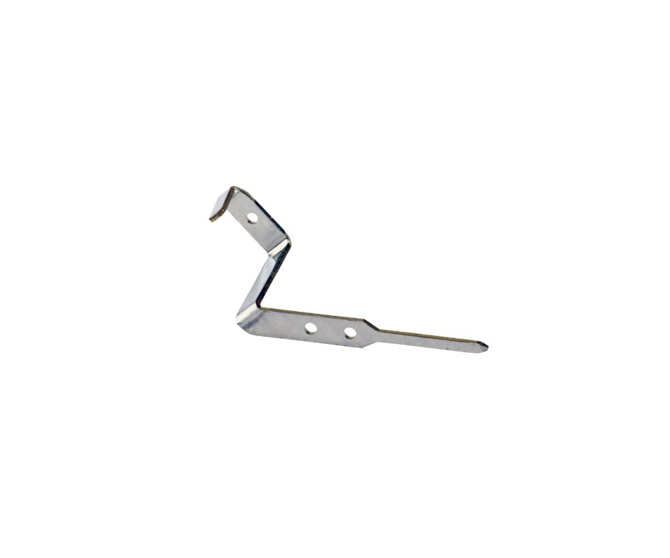
- Substitute the terminal alloy from C51000 phosphor bronze to C17200 beryllium copper mill-hardened temper for applications with a confirmed operating ambient above 85°C. The material cost increase is 3× to 5× but eliminates intermittent field failures that carry warranty costs exceeding the material premium by 10× to 50× per incident.
- Specify C51000 with a pre-stressed heat treatment at 150°C for 2 hours after forming. This low-temperature anneal relaxes the peak residual stress at the bend root without reducing the bulk yield strength by more than 5%. The pre-stressing step reduces subsequent relaxation rate by 20% to 30%.
- Modify the progressive die to increase the number of bend stages from one to two. A two-stage bend — rough form at 45 degrees followed by final form at 90 degrees — distributes the plastic strain across a wider bend zone and reduces peak residual stress by 15% to 25% compared to a single-stage bend.
- Replace the PBT connector housing with a PPA or PPS material rated for 180°C continuous service when the terminal operating temperature exceeds 120°C. The housing stiffness at temperature prevents terminal cavity movement that shifts the contact beam off its designed deflection point.
For terminals already in production where tooling modifications are not feasible within the current program timeline, contact progressive die tooling engineering for a coining insert design that retrofits into the existing bend station with a single-punch replacement.
Verification Protocol
Thermal Aging Test
Conduct isothermal aging per ASTM E328 at three temperatures — the rated maximum operating temperature, rated maximum plus 15°C, and rated maximum plus 30°C — for a minimum of 1,000 hours each. Sample size is 30 terminals per temperature drawn from three production lots to capture lot-to-lot temper variation within the alloy specification.
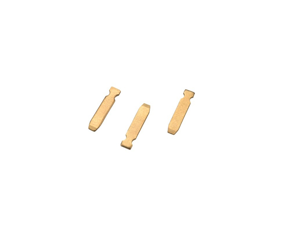
Remove 10 terminals from each temperature chamber at 100-hour intervals for the first 500 hours, then at 250-hour intervals for the remainder. Measure the contact force at 0.5 mm, 1.0 mm, and 1.5 mm deflection using a force gauge with 0.01 N resolution. Plot the force retention percentage against a log-time scale to verify the linear Larson-Miller relationship that validates the extrapolation to end-of-life.
A terminal design that retains 85% or more of initial contact force at the rated maximum temperature after 1,000 hours passes the relaxation verification. If the force drops below 85% at the rated maximum plus 30°C condition, the design has insufficient margin for transient overtemperature events and requires one of the corrective adjustments from the previous section.
USCAR-2 Validation
Submit 10 terminals from the post-aging sample to the USCAR-2 Class 2 vibration and thermal shock sequence. Measure contact resistance at insertion cycles 1, 10, and 30 after the environmental exposure using four-wire Kelvin measurement at 100 mA.
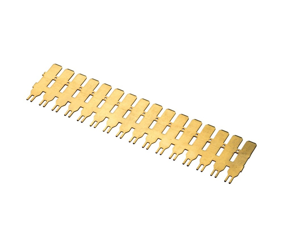
A contact resistance shift exceeding 2 mΩ from the pre-exposure baseline confirms that the residual contact force is insufficient for the vibration and temperature conditions of the intended vehicle environment.
Stress Relaxation Design Review: Kravzik’s application engineering team reviews your terminal contact beam design — including alloy grade, bend radius, coining specification, and operating temperature profile — and returns a relaxation life projection with ranked corrective actions if the predicted force retention falls below the 85% threshold at the rated service temperature. Send your terminal design data for a stress relaxation review with force retention projections.
Fix & Verify
Substituting C17200 beryllium copper to fix relaxation without adjusting bend radius for the higher yield strength causes cracking during insertion. Kravzik’s material engineering team validates alloy substitutions with a bend-formability matrix and force-deflection profiling across the full operating temperature range before tooling steel is cut.
Send your terminal drawing for a complete stress relaxation analysis with alloy comparison, bend radius optimization, and USCAR-2 validation, delivered within 72 hours.