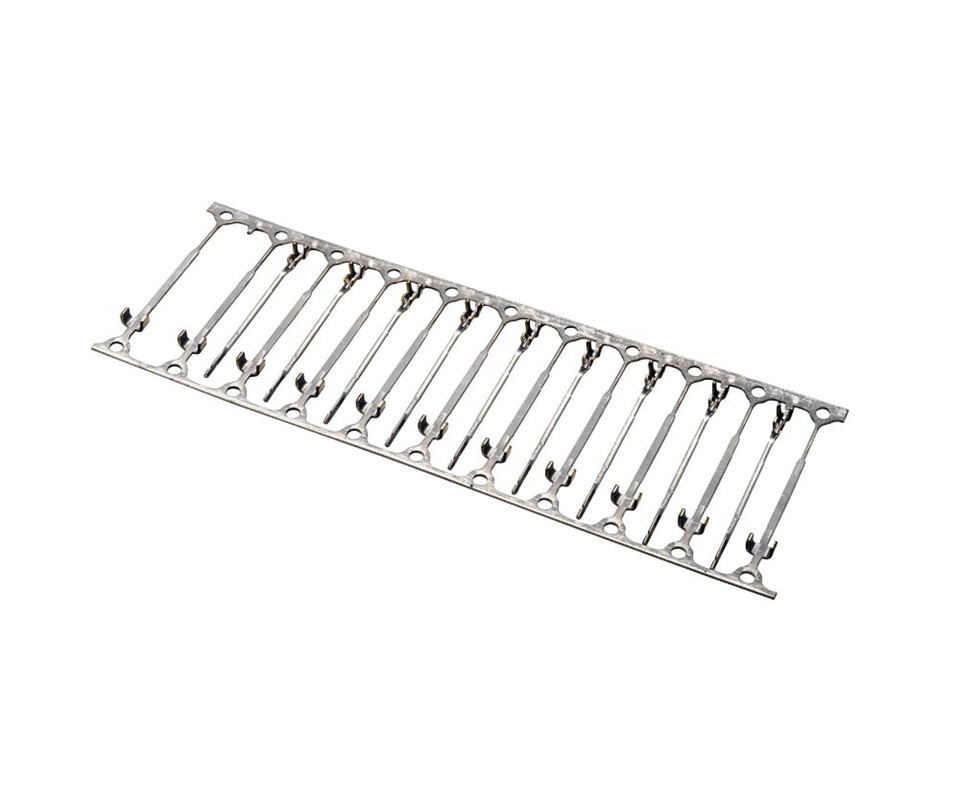
A reel of tin-plated electrical terminals passes visual inspection and XRF thickness measurement at final QC, ships to the connector assembly line, and produces plating flakes on the insertion tooling within the first 50 cycles. Under 20× magnification, the flake zone shows exposed C26000 brass substrate with no tin intermetallic layer at the interface — confirming that the plating never bonded to the base metal — and the entire reel is rejected, halting the assembly line for a material quality investigation.
In this analysis, you will learn how to diagnose plating adhesion failure across three root cause categories — surface contamination from stamping oil and handling residues, cleaning process chemical depletion, and plating bath activation and nucleation — with corrective process controls verified through thermal shock testing and cross-section metallography.
Read on for the full root cause analysis.
Adhesion Symptom
Plating adhesion failure on stamped electrical terminals presents as tin delamination at the contact interface during insertion cycling, producing visible flakes 0.1 mm to 0.5 mm in diameter on the connector housing and insertion tooling. The delamination exposes the copper alloy substrate, which oxidizes within hours and produces a contact resistance rise from the 5 mΩ specification to 50 mΩ or higher within 100 insertion cycles.
The failure is often misdiagnosed as tin fretting corrosion because the end result — high contact resistance with visible surface degradation — is identical. The diagnostic distinction is the insertion cycle count at failure onset: plating adhesion failure produces flakes and resistance rise within 10 to 50 cycles, while fretting corrosion requires 100 to 500 cycles of micro-motion to generate insulating oxide debris at the contact interface.
Cross-Section Analysis
Mount an un-inserted terminal in epoxy, cross-section through the contact zone, polish to a 1 µm diamond finish, and etch with ammonium hydroxide and hydrogen peroxide for 5 seconds. Examine the tin-to-copper interface at 500× under an optical microscope.
A continuous Cu₆Sn₅ intermetallic compound layer 1 µm to 2 µm thick at the interface confirms metallurgical bonding. A gap, void line, or contaminant film at the interface with no intermetallic layer confirms an adhesion failure — the tin deposit is mechanically attached but not metallurgically bonded.
Scanning electron microscopy with EDS at the interface identifies the contaminant chemistry. Carbon-rich spectra indicate stamping oil residue.
Silicon-rich spectra indicate mold release or handling contamination. Oxygen-rich spectra with no intermetallic layer indicate that the terminal surface oxide was not removed by the acid activation step before plating.
Root Cause Categories
Surface Contamination
Stamping oil residue is the most common surface contaminant causing plating adhesion failure. Progressive die stamping of copper alloy strip at 400 to 800 SPM deposits 1 mg to 5 mg of stamping oil per terminal — a mixture of mineral oil, chlorinated paraffin extreme-pressure additives, and ester-based boundary lubricants.
The oil film must be reduced to below 0.1 mg per terminal before the terminal enters the plating bath, or the tin deposit nucleates on the oil film rather than the copper substrate.
Handling contamination introduces a second class of adhesion inhibitor. Operators loading stamped terminals into plating barrels with bare hands deposit skin oils and salts that create localized non-wetting zones on the terminal surface.
The resulting adhesion failure pattern is non-uniform — isolated flake zones 2 mm to 5 mm in diameter corresponding to finger contact areas — which distinguishes handling contamination from the uniform adhesion failure pattern of stamping oil residue.
Storage between stamping and plating introduces oxidation that cleaning processes must remove. Copper alloy strip stored in ambient air at 50% relative humidity develops a Cu₂O oxide layer 5 nm to 10 nm thick within 24 hours.
After 7 days, the oxide thickness reaches 20 nm to 30 nm and begins incorporating atmospheric sulfur compounds that form a tenacious Cu₂S film resistant to acid activation. Terminals stored longer than 72 hours between stamping and plating require a stronger acid activation step to remove this sulfide-contaminated oxide.
Cleaning Process Degradation
Alkaline electrocleaner depletion is the most common cleaning process failure. The electrocleaner removes stamping oil by saponification of ester-based lubricants and emulsification of mineral oil components.
As the cleaner processes thousands of terminals, the concentration of saponified oil builds up, the free alkalinity drops, and the cleaning efficiency degrades. A cleaner bath that removes 98% of stamping oil at the start of its service life may remove only 60% after processing 500,000 terminals if the bath chemistry is not replenished.
Rinse water contamination between cleaning and activation steps carries over alkaline cleaner residue into the acid activation bath. When the drag-out from the cleaner tank raises the pH of the activation bath above 3.0, the acid is partially neutralized and the oxide removal reaction slows to a rate insufficient to expose bare copper metal before the parts enter the plating bath.
The activation bath must be dumped and recharged when the pH exceeds 2.5 to maintain the required oxide removal rate.
Final rinse water quality before plating is the last process variable before tin deposition. DI water with conductivity above 10 µS/cm contains dissolved ionic species — primarily sodium, chloride, and sulfate from the preceding process baths — that adsorb onto the activated copper surface and inhibit tin nucleation.
Each 5 µS/cm increase in rinse water conductivity above the 10 µS/cm threshold reduces plating adhesion strength by approximately 15% as measured by the tape test.
Plating Bath Activation
The acid activation step immediately before plating is the chemical process that determines whether the tin deposit bonds metallurgically or mechanically. A 5% to 10% sulfuric or methanesulfonic acid dip at room temperature for 15 to 30 seconds removes the oxide layer from the copper alloy surface and leaves an active metallic surface with high surface energy for tin nucleation.
The activation step is self-limiting — once the oxide is removed, the acid does not attack the bare copper at room temperature within the 30-second window.
Activation bath aging is the time-dependent variable most frequently overlooked. As the bath processes terminals, dissolved copper concentration builds from 0 ppm to 200 ppm to 500 ppm, and the copper ions in solution plate onto the terminal surface through an immersion displacement reaction with the less-noble base metal components — zinc in brass, tin in phosphor bronze.
This immersion copper layer is porous and non-adherent, and the tin deposit subsequently nucleates on the loose copper particles rather than the base alloy, producing a mechanically weak interface.
Deep Dive: Explore plating process control for electrical terminals — including Hull cell testing for bath chemistry monitoring, cyclic voltammetric stripping for organic contaminant detection, and adhesion test method selection per ASTM B571 for production lot acceptance — to establish a closed-loop plating quality system.
💡 Plating Adhesion Process Audit: Kravzik’s plating engineering team reviews your terminal plating line — including cleaner concentration and titration records, rinse water conductivity logs, acid activation bath chemistry and copper loading, and plating bath cathode efficiency — and returns an adhesion failure risk assessment with process control recommendations. Submit your plating process data for an adhesion failure root cause analysis.
Process Adjustments
Non-Destructive Adjustments
These adjustments modify the existing plating line parameters without chemical reformulation or equipment modifications.
- Increase alkaline electrocleaner concentration to the upper limit of the supplier’s recommended range — typically 8% by volume — and verify free alkalinity by titration at the start of each shift. Replenish with fresh concentrate when free alkalinity drops below 75% of the starting value.
- Increase electrocleaner current density from 2 A/dm² to 5 A/dm² for 30 seconds. The higher current density increases hydrogen gas evolution at the terminal surface, which provides mechanical scrubbing action that dislodges oil residue from surface micro-crevices. Verify that the higher current does not cause surface pitting on the terminal at 20× magnification.
- Reduce the time between stamping and plating to under 48 hours. If production scheduling prevents this, store stamped terminals in sealed bags with desiccant to limit oxide growth, and extend the acid activation dwell time from 30 seconds to 45 seconds to compensate for the thicker oxide layer.
- Replace DI water resin cartridges in the final rinse station when conductivity reaches 5 µS/cm — half of the 10 µS/cm maximum — to maintain a margin for conductivity drift between cartridge change intervals. Install an in-line conductivity meter with an alarm set at 8 µS/cm to alert operators before the limit is reached.
Process and Equipment Adjustments
These adjustments require chemical reformulation, equipment modifications, or plating line reconfiguration.
- Dump and recharge the acid activation bath when dissolved copper concentration reaches 200 ppm, measured by atomic absorption spectroscopy or ICP-OES at weekly intervals. The 500 ppm threshold widely cited in plating handbooks is a maximum for non-critical decorative plating — electrical terminals with a 2 µm to 5 µm tin thickness require the tighter 200 ppm limit because the thin deposit provides no margin for adhesion weakness at the interface.
- Install an ultrasonic agitation system in the alkaline cleaner tank operating at 40 kHz with a power density of 10 W/L. Ultrasonic cavitation at the terminal surface generates micro-jets that dislodge oil residue from crevices, coined features, and cut edges that electrocleaner current alone cannot reach. The adhesion improvement is most pronounced on terminals with coined features deeper than 0.05 mm.
- Add a 5% to 10% sulfuric acid pre-dip with 30-second dwell time immediately before the plating bath for terminals stored longer than 48 hours after stamping. The pre-dip provides a second oxide removal step after the primary activation bath and eliminates the oxide regrowth that occurs during the transfer time between the activation station and the plating bath inlet.
- For C17200 beryllium copper terminals, add a nickel underplate 0.5 µm to 1.0 µm thick between the copper substrate and the tin topcoat. The nickel layer acts as an adhesion promoter because tin nucleates more readily on nickel than on beryllium copper’s beryllium-oxide-rich surface, and the nickel interlayer also serves as a diffusion barrier that slows copper-tin intermetallic growth during thermal aging.
For terminals where plating adhesion failures have triggered a customer corrective action report, contact progressive die tooling and plating process engineering to conduct a joint root cause analysis that traces the failure from the terminal surface condition at the press exit through every process step to the plating bath exit.
Verification Protocol
Thermal Shock Adhesion Test
Conduct thermal shock testing per ASTM B571 on 10 terminals per plating lot. Cycle the terminals between −55°C and 150°C with a 15-minute dwell at each temperature extreme and a transfer time under 30 seconds for 100 cycles.
The thermal expansion mismatch between tin (CTE 23 µm/m°C) and copper alloy (CTE 17 µm/m°C) generates interfacial shear stress of approximately 15 MPa to 25 MPa per cycle — sufficient to delaminate a mechanically attached deposit but not a metallurgically bonded intermetallic interface.
Apply a pressure-sensitive tape per ASTM D3359 Method B to the contact zone of each terminal after thermal shock. Peel the tape at a 180-degree angle at a uniform rate.
Zero visible plating removal on the tape confirms metallurgical bonding. Any tin transfer to the tape, regardless of area, constitutes an adhesion failure and the plating lot is rejected.
Bend Adhesion Test
Bend 5 terminals from the post-thermal-shock sample through a 90-degree angle around a mandrel with a radius equal to the terminal material thickness. Examine the bend apex under 20× magnification.
Cracking of the tin deposit at the bend tension surface is acceptable — the tin layer fractures because its ductility is lower than the copper alloy substrate — but flaking, spalling, or separation of the tin from the substrate at the crack edge indicates adhesion failure.
Cross-section one terminal from the bend test at the apex and examine the tin-to-copper interface under SEM at 2,000×. A continuous intermetallic layer through the bend zone with no interfacial separation confirms that the plating adhesion survived the maximum mechanical deformation the terminal will experience in service.
An interfacial crack extending from the tin surface crack into the substrate interface indicates insufficient adhesion for the application’s mechanical requirements.
✅ Plating Line Process Qualification: Kravzik’s plating engineering team qualifies your terminal plating process for adhesion integrity — including cleaner efficiency testing, rinse water conductivity profiling, activation bath copper loading analysis, and ASTM B571 thermal shock adhesion testing with cross-section metallography of any failed specimens. Submit your plating process parameters for an adhesion failure root cause analysis with corrective action recommendations.
Fix & Verify
Recharging the acid activation bath to fix adhesion can over-etch grain boundaries and create sub-surface voids that delay but do not prevent failure. Kravzik’s closed-loop plating line titrates cleaner per shift, monitors rinse conductivity in-line, dumps the activation bath at 200 ppm copper, and tests every lot with zero-failure ASTM B571 thermal shock.
Send your terminal plating specification for a complete plating adhesion failure analysis with cleaning process audit, activation bath optimization, and ASTM B571 lot acceptance testing, delivered within 72 hours.