A progressive die built to the CAD nominal angle produces a terminal with a contact beam bent to 87 degrees instead of 90 — the 3-degree springback shifts contact normal force from 3.0 N to 2.5 N, below the 2.7 N minimum in the connector specification. The tooling modification costs $5,000 to $8,000 and delays production qualification by 3 weeks.
In this guide, you will learn alloy-specific springback factors for copper terminal stock, die overbend angle calculation, bend sequencing strategies, and coining methods that stabilize grain structure to eliminate springback-driven die rework.
Read on for the full DFM guide.
Fundamental Geometry & Material Behavior
Springback Mechanism & Alloy Behavior
Springback is the elastic recovery that occurs when a bent terminal is released from the forming punch and die. During bending, the outer surface of the bend radius stretches plastically while the inner surface compresses. A central elastic core —approximately 2040% of the material thickness —remains below the yield point and attempts to return to its original shape when the forming force is removed.
This elastic recovery manifests as an angular deviation from the tool angle, typically 2 to 8 degrees for copper alloy terminal stock at 0.20 to 0.80 mm thickness.
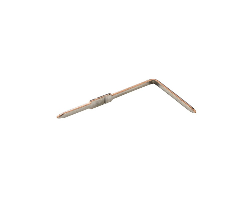
The springback magnitude depends on four variables: the alloy’s yield strength-to-elastic modulus ratio, the bend radius-to-thickness ratio, the bend angle, and the material’s temper condition. Phosphor bronze C51000 at half-hard temper with a yield strength of 480 MPa and elastic modulus of 110 GPa produces 2.0 to 2.5 degrees of springback per 90-degree bend at R/t of 1.0. Beryllium copper C17200 at half-hard temper with a yield strength of 760 MPa and the same 110 GPa modulus produces 5.0 to 5.5 degrees —more than double the springback at the same thickness and bend radius.
The springback factor correlates directly with the yield-to-modulus ratio for stamped electrical terminals in production forming.
Bend Radius-to-Thickness Ratio
The bend radius-to-thickness ratio is the second-order variable that catches inexperienced die designers. At R/t below 1.0 —a sharp bend where the inner radius equals the material thickness —the plastic strain through the thickness is high enough to minimize the elastic core, keeping springback predictable. At R/t above 2.0, the elastic core occupies a larger fraction of the cross-section, and springback increases non-linearly.
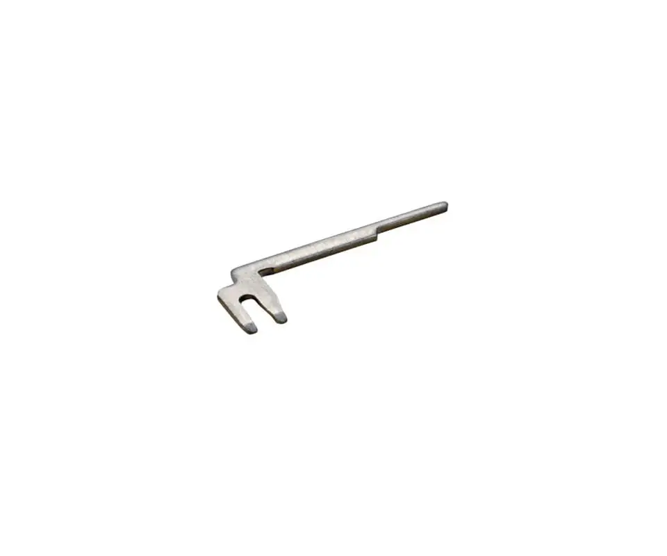
A terminal with a 0.30 mm bend radius in 0.20 mm stock (R/t = 1.5) springs back 3.5 degrees. The same terminal with a 0.50 mm bend radius (R/t = 2.5) springs back 6.0 degrees —a near-doubling of springback for a 0.20 mm radius increase.
[CAD Takeaway]: Specify bend radius at or below 1.5× material thickness on all formed features to maintain springback below 4 degrees per 90-degree bend for copper alloy terminal stock.
Die Compensation & Tooling Mechanics
Overbend Compensation Calculation
The die must overbend the terminal past the nominal angle by the exact springback amount so that elastic recovery brings the part to the drawing specification. This overbend compensation is built into the forming punch and die geometry —not adjusted by press settings. For C51000 phosphor bronze at 0.25 mm thickness with a 90-degree bend, the die forming angle is set to 92.5 degrees (2.5 degrees of overbend compensation).
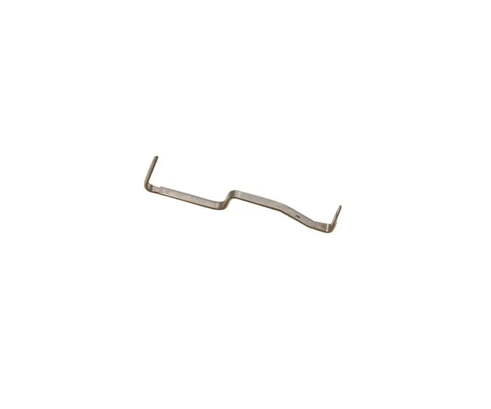
The terminal springs back 2.5 degrees after ejection and lands at 90 degrees on the CMM inspection report.
Sequence-Dependent & Coining Compensation
The compensation angle is alloy-specific, thickness-dependent, and must account for the work-hardening that occurs during progressive die forming. A terminal that passes through piercing stations before reaching the forming station has accumulated cold work that increases the material’s yield strength locally —increasing springback by 0.5 to 1.5 degrees compared to virgin strip. Experienced die designers at Kravzik apply a forming-sequence-dependent springback factor that accounts for upstream work-hardening, rather than using a single alloy-specific compensation value for the entire die.
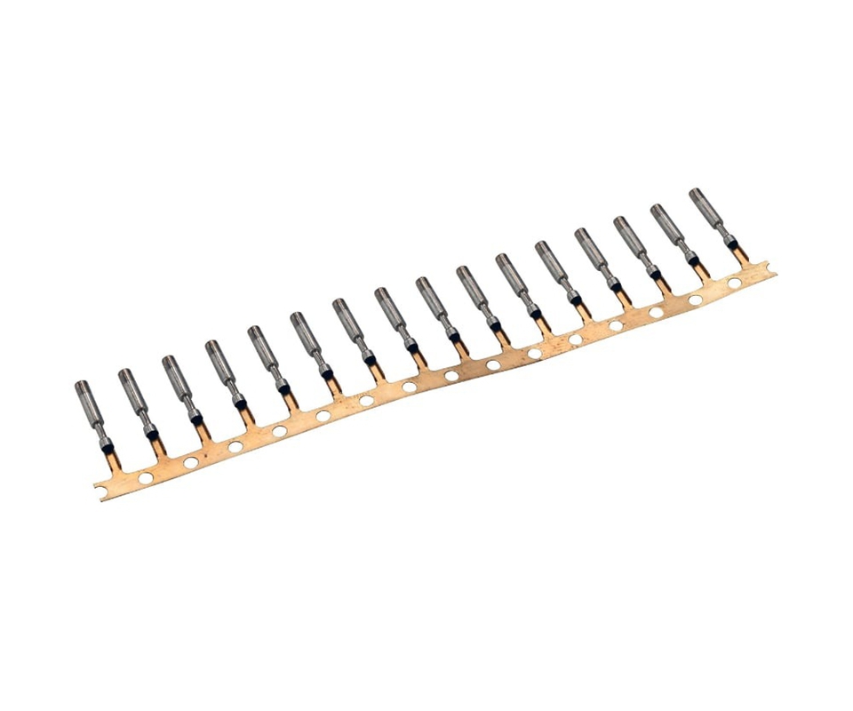
This sequenced compensation approach is critical for electrical stamping parts where multiple bends on the same terminal interact through residual stress redistribution across different die stations.
Coining at the bend line —a localized compression of 1015% of material thickness applied by a coining station immediately before the forming station —reduces springback by 3050% across coil-to-coil material variation. The coining operation compresses and stabilizes the grain structure at the bend line, reducing the yield strength gradient through the thickness that drives springback variation. For stamped electrical terminals in high-volume production where coil-to-coil material property variation can shift springback by 1.0 to 2.0 degrees, a coining station at the bend line is standard practice —it costs one additional die station and eliminates the springback variation that would otherwise require die angle adjustments between material lots.
[CAD Takeaway]: Include a coining station at every bend line in the progressive die strip layout, specifying 10–15% thickness reduction, to reduce coil-to-coil springback variation by 30–50%.
Precision, Tolerancing & Bend Sequence
Bend Sequence Planning
Bend sequence —the order in which multiple bends are formed on a single terminal —affects the final angle of every bend. When bend A is formed first and bend B second, the plastic deformation of bend B redistributes residual stress in the terminal body, partially relaxing the stress that holds bend A at its formed angle. The result: bend A springs back an additional 0.5 to 1.0 degree beyond its compensated angle after bend B is formed.
This sequence-dependent springback shift is invisible if the die tryout measures each bend in isolation but becomes apparent when the terminal is measured as a complete formed part.
The correct bend sequence places the most functionally critical bend last in the progression, so that no subsequent forming operation disturbs its residual stress state. For a stamped electrical terminal with a contact beam bend (functionally critical —controls normal force) and a retention lance bend (less critical —controls insertion force within a wider tolerance band), the contact beam is formed last. This sequencing ensures that the contact beam angle, measured at the CMM after the terminal exits the die, matches the compensated die angle within 0.5 degrees.
The retention lance bend, formed earlier in the sequence, absorbs the 0.5-degree springback shift from the contact beam forming operation —a shift that is within the lance’s wider tolerance band.
Angular Tolerance Specification
Dimensional tolerance on the formed angle is specified as an angular tolerance with a reference gauge length. A specification of “90° ±1° at 3.0 mm gauge length” means the terminal’s contact beam must be within 1 degree of perpendicular measured at a point 3.0 mm from the bend centerline. This gauge-length-dependent tolerance is critical for short contact beams.
A 0.5-degree angular error at a 2.0 mm gauge length produces a 0.017 mm positional deviation. The same 0.5-degree error at a 6.0 mm gauge length produces a 0.052 mm deviation —exceeding the typical ±0.03 mm positional tolerance for stamped electrical contacts in high-density connectors.
[CAD Takeaway]: Specify angular tolerance with the gauge length explicitly called out on the drawing, and ensure the gauge length corresponds to the functional contact point location on the formed terminal beam.
Defect Avoidance & Die Tryout Protocol
Common Springback Defects
The three most common springback-related defects in progressive die stamping are under-bend, over-bend, and twist. Under-bend occurs when the die compensation angle is too small —the terminal springs back past the nominal angle and the contact beam is too open. Over-bend occurs when the compensation is too large —the contact beam is too closed and the connector insertion force exceeds specification.
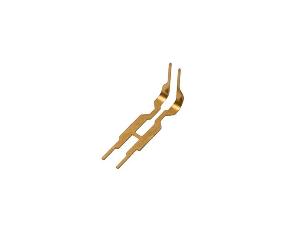
Twist occurs when the bend line is not perpendicular to the strip grain direction, causing the terminal to rotate out of plane after the forming punch retracts due to anisotropic springback.
Die Tryout & Grain Direction Protocol
The die tryout protocol catches these defects before the die ships to production. Kravzik‘s die tryout procedure for stamped electrical terminal forming includes the following. First article inspection measures the formed angle on 30 consecutive terminals at die startup using a vision measurement system with 0.1-degree resolution.
The mean angle must fall within 0.5 degrees of nominal, and the range across 30 samples must stay below 0.5 degrees —a process capability equivalent to Cpk of 1.33 at ±1.0-degree tolerance. If the mean angle is off by more than 0.5 degrees, the die compensation angle is adjusted by re-grinding the forming punch at the correct overbend angle —a 2-hour die maintenance operation rather than a die rework.
Grain direction orientation is a die layout decision, not a press adjustment. Bending perpendicular to the grain direction produces lower and more consistent springback than bending parallel —typically 1.0 to 2.0 degrees less for copper alloy strip. The terminal blank must be oriented on the strip so that all functionally critical bends are perpendicular to the rolling direction.
Bends parallel to the grain direction are permitted only on non-functional features where 2.0 to 3.0 degrees of additional springback variation is acceptable. [CAD Takeaway]: Orient all contact beam and retention lance bends perpendicular to the material grain direction in the strip layout to minimize springback and eliminate twist defects during stamped terminal forming.
[CAD Takeaway]:
CAD to Production
Trial-and-error springback compensation during die tryout consumes days of press time and delays PPAP submission with every iterative grind cycle. Kravzik’s die design process models alloy-specific springback using FEA simulation before tool steel is cut, producing formed terminals within 0.5 degrees of nominal on the first tryout.
Send your terminal bend geometry for a springback-compensated die design with FEA-validated forming angles and die tryout protocol, returned within 3 business days.