A progressive die stamping C51000 phosphor bronze at 500 strokes per minute produces 30,000 terminals per hour with burr height under 0.008 mm — three weeks later, the same die produces burrs of 0.025 mm, enough to trigger an IQC rejection and increase connector insertion force by 30%. The die clearance hasn’t changed — the punch edge radius has.
In this guide, you will learn the die clearance optimization, punch sharpening protocol, burr direction control, and material-specific stamping parameters that maintain burr height below 0.01 mm across the full production life of a progressive die for stamped electrical terminals.
Read on for the full DFM guide.
Fundamental Geometry & Die Clearance
Burr Formation Mechanics
Burr formation in progressive die stamping is a shear mechanics problem. As the punch descends and contacts the strip surface, the material undergoes elastic compression, then plastic deformation, and finally fracture propagation along the die clearance gap. The fracture initiates at the punch corner and die corner simultaneously and propagates toward the center of the material thickness.

When the two fracture fronts meet cleanly, the result is a characteristic shear edge with rollover, burnish, fracture, and burr zones. The burr — a thin ridge of deformed material at the edge of the fracture zone — is the fingerprint of the clearance condition at the moment of fracture.
Alloy-Specific Clearance Optimization
Die clearance — the gap between punch and die on each side of the cut — is the primary variable controlling burr height. For copper alloy terminal stock at 0.20 to 0.80 mm thickness, optimal clearance is 5 to 8 percent of material thickness per side. At 5 percent clearance, the fracture fronts meet at the center of the material thickness and produce a burr height of 0.005 to 0.010 mm.

At 12 percent clearance, the fracture fronts miss each other and the material tears rather than shears cleanly. This produces burr height of 0.020 to 0.035 mm. At 3 percent clearance, the fracture initiates late and produces secondary shear. This generates a burr of 0.015 to 0.025 mm from the double-cut effect for electrical stamping parts in high-speed progressive dies.
The clearance window is alloy-specific because different alloys have different fracture characteristics. Brass C26000 with its lower ductility produces acceptable burr height across a wider clearance window of 5 to 12 percent. Phosphor bronze C51000, which work-hardens rapidly during the shear process, requires a tighter window of 5 to 8 percent.
Beryllium copper C17200 at age-hardened temper requires 4 to 6 percent — the narrowest window due to its high yield strength and low ductility.
[CAD Takeaway]: Specify die clearance at 6 percent of material thickness per side for phosphor bronze and beryllium copper terminal alloys, and verify clearance on both punch-to-die sides with a feeler gauge at every 100,000-stroke maintenance interval.
Tooling Wear & Sharpening Protocol
Edge Wear Mechanism & Sharpening Trigger
Punch and die edge radius increases with every stroke as the cutting edges abrade against the copper alloy strip. A new punch with a 0.005 mm edge radius produces burr height of 0.006 mm at 6 percent clearance. After 300,000 strokes, the edge radius has grown to 0.015 mm. The effective clearance at the cutting interface has increased because the radiused edge behaves like a larger clearance, shifting the fracture initiation point and increasing burr height to 0.012 to 0.015 mm for stamped electrical terminal production.
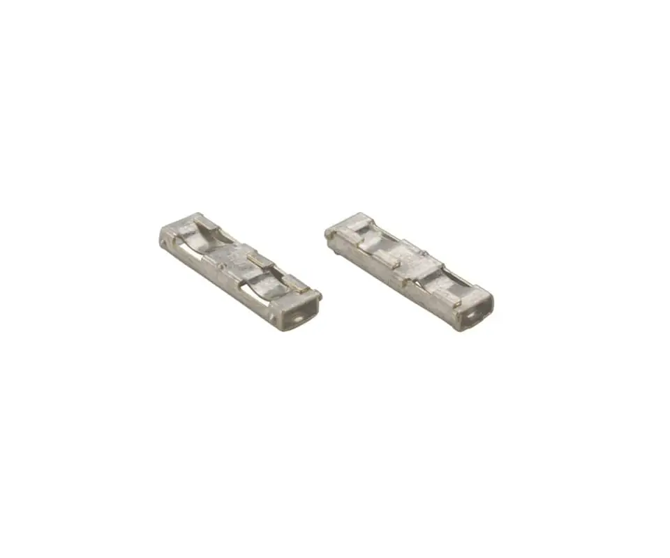
The correct sharpening trigger is burr height, not stroke count. A die stamping C19400 at 0.30 mm thickness may run 800,000 strokes before burr height crosses the 0.015 mm threshold. The same die stamping C17200 at 0.40 mm thickness crosses the threshold at 300,000 strokes. This is because stamped electrical terminal alloys like C17200 have higher yield strength accelerating punch edge wear
Measurement Protocol & Punch Lifecycle
Kravzik‘s die maintenance protocol measures burr height at 50,000-stroke intervals using laser profilometry with 0.001 mm resolution. When burr height crosses 0.015 mm, the punch set is removed for sharpening — a 2-to-4-hour operation that restores the edge radius to below 0.005 mm and returns burr height to the 0.005 to 0.008 mm range for the next production interval.

The sharpening protocol must account for the punch’s progressive diameter loss. Each sharpening removes 0.02 to 0.05 mm from the punch face. After 10 sharpening cycles, the punch is 0.2 to 0.5 mm shorter. This shifts the forming timing relative to other stations and may require a shim adjustment at the punch holder.
After 20 to 30 sharpening cycles, the punch diameter reduction through the working length affects the die clearance and the punch must be replaced. A well-maintained progressive die for terminal stamping typically runs 2 to 5 million strokes per punch set before replacement, with sharpening every 300,000 to 800,000 strokes depending on the alloy being stamped.
[CAD Takeaway]: Establish the burr height sharpening threshold at 0.015 mm for contact-interface edges and 0.025 mm for non-functional edges; measure at 50,000-stroke intervals with laser profilometry; replace punches after 20 sharpening cycles or when the diameter loss exceeds 3 percent of nominal.
Burr Direction & Strip Layout Strategy
Burr Direction Assignment by Feature
Burr direction is a die layout decision made before the first piece of tool steel is cut. The burr always forms on the punch exit side of the strip — the side facing away from the punch entry surface. If the terminal blank is pierced from the top side of the strip, the burr forms on the bottom surface.

If a forming station then bends the terminal downward, the burr ends up on the inside of the bend. It is oriented away from the contact interface and connector housing ramp. This intentional burr direction control is standard practice for stamped electrical connectors where the terminal slides against a plastic housing during insertion.
The strip layout must assign burr direction to every pierced and blanked feature based on its functional role. Contact beam edges that slide against the mating terminal — burr must face away from the contact interface. Insertion edges that slide against the connector housing ramp — burr must face away from the ramp surface.
Wire crimp barrel edges — burr direction is non-critical because the wire strands embed into the crimp and the burr is crushed into the barrel interior. This feature-level burr direction assignment is documented on the strip layout drawing and locked into the die design at the punch entry direction for each station.
Insertion Force Impact of Burr Orientation
A correctly oriented burr can reduce insertion force. When the burr faces the trailing side of the insertion direction — the side opposite the housing ramp — the smooth burnished edge of the shear zone contacts the ramp instead of the burr.

In a terminal designed for sub-3 N insertion force, burr direction control can reduce insertion force by 0.5 to 1.0 N compared to a randomly oriented burr — a difference that determines whether the connector passes the insertion force specification.
[CAD Takeaway]: Assign burr direction on the strip layout for every functionally critical edge; contact interface burr must face away from the mating surface; insertion edge burr must face away from the housing ramp; document burr direction with arrows on the strip layout drawing.
This burr orientation strategy becomes critical in multi-pin connectors where 40 to 60 terminals are inserted simultaneously into a housing. The cumulative insertion force is the sum of individual terminal forces, and a 0.5 N per-terminal difference across 60 positions shifts the total insertion force by 30 N. This is enough to require a pneumatic assist cylinder instead of manual insertion on the harness assembly line. Correct burr direction assignment at the strip layout stage eliminates this downstream assembly cost adder before the first terminal is produced.
Material Variation & Clearance Compensation
Design-for-Hardest-Coil Strategy
Coil-to-coil material property variation is the variable that turns a well-designed die clearance into a burr problem. Copper alloy strip is supplied to a temper specification that permits a hardness range of ±15 HV within a single temper designation. A die clearance optimized at 6 percent for C51000 phosphor bronze at 180 HV produces burr height of 0.006 mm.

When the next coil arrives at 195 HV — within the half-hard temper specification but 15 HV harder — the same 6 percent clearance produces burr height of 0.012 mm because the harder material fractures later in the punch stroke, shifting the fracture front intersection point.
The die must be designed for the hardest expected coil within the alloy specification range, not the average. If the clearance is set for the hardest coil (6 percent at 195 HV), the softer coils will produce slightly higher burr height (0.008 to 0.010 mm) but still within the acceptable range. If the clearance is set for the average coil, the hard coils produce unacceptable burr height and force unplanned die maintenance.
This design-for-hardest-coil approach prevents the emergency punch sharpening events that disrupt production scheduling for electrical stamping components in high-volume programs with just-in-time delivery requirements.
Incoming Coil Verification Protocol
Incoming coil hardness verification closes the loop. Kravzik measures the Vickers hardness of each incoming coil at three locations across the strip width and compares against the die clearance specification. If the coil hardness is more than 10 HV above the die’s design hardness, the die clearance is adjusted by shimming the die block — a 30-minute adjustment at the press rather than a punch sharpening event.

This incoming inspection protocol prevents the scenario where a hard coil enters production undetected and produces 50,000 terminals with burr height exceeding 0.020 mm before the in-die vision system catches the trend.
[CAD Takeaway]: Design die clearance for the maximum expected coil hardness in the alloy specification range, and implement incoming coil hardness verification at the press with a 10 HV trigger for clearance adjustment.
CAD to Production
Burr height excursions at customer incoming inspection trace back to die clearance optimized for the first coil and never re-validated. Kravzik’s die design includes a burr control plan specifying clearance by alloy, burr direction per feature, and sharpening thresholds validated with 30-piece capability studies.
Send your terminal blank drawing for a burr control die design with alloy-specific clearance specification and sharpening threshold plan, returned within 3 business days.