A stainless steel spring clip that sits 0.05 mm off-center in the terminal retention slot passes the snap-in feel test at the press line —then releases at 1,200 thermal cycles, backing the terminal out of the sealed automotive connector housing. The inline camera never caught the misalignment. The warranty claim caught it at $18 per vehicle across 40,000 units.
In this guide, you will learn in-die staking mechanics, component feeding synchronization, station planning for progressive die tooling, and validation protocols for terminals that ship finished from the press exit with zero secondary labor.
Read on for the full DFM guide.
Fundamental Geometry & Staking Mechanics
Retention Slot Design & Clearance Rules
In-die assembly begins at the terminal design stage, not the die design stage. The terminal body must include retention features — slots, tabs, or coined recesses — that mechanically capture the secondary component during the staking stroke. A retention slot for a 0.15 mm thick stainless steel spring leg must be pierced at 0.18 to 0.22 mm width — providing 0.03 to 0.07 mm of clearance for the spring leg to enter the slot before staking deforms the slot edges into mechanical interlock.
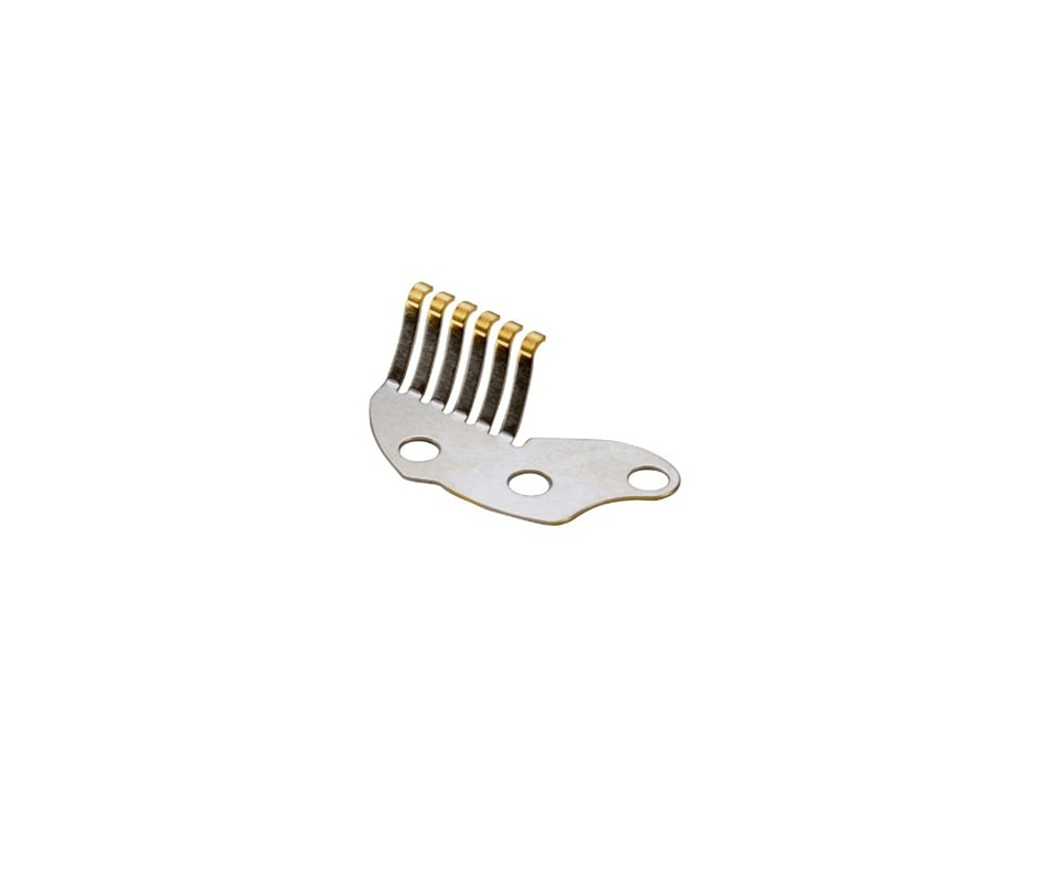
Too tight and the spring leg binds during feeding. Too loose and the staked material does not close the gap, leaving the spring leg free to disengage under vibration.
Staking Force & Punch Geometry
The staking operation deforms a localized volume of the terminal body material — typically a tab or lip adjacent to the retention slot — by 30 to 50 percent of its thickness. When the staking punch descends, it displaces the terminal material laterally into the retention slot, closing the clearance gap around the spring leg and creating a mechanical interlock. The staking force required is 3 to 5 times the force needed to pierce the same material thickness, because staking displaces material laterally against constraint rather than shearing through it.
For a C51000 phosphor bronze terminal body at 0.40 mm thickness with a 2.0 mm wide staking tab, the staking force is approximately 800 to 1,200 N at one station. This force gets added to the press tonnage budget for copper alloy terminals with in-die assembly operations.
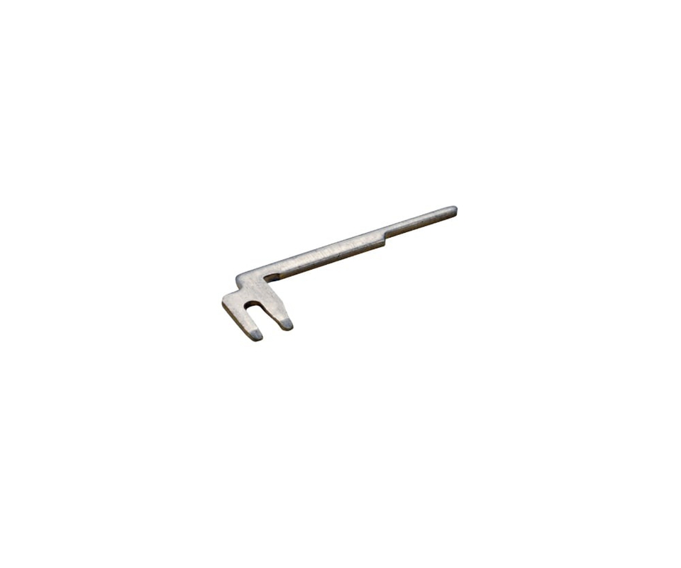
The staking punch geometry determines whether the staking operation succeeds or cracks the terminal body. A flat-faced staking punch produces uncontrolled material flow that can crack the terminal at the slot corners. A radiused punch face with a 0.10 to 0.15 mm radius and a 10 to 15-degree lead-in angle directs material flow toward the slot centerline, reducing the tensile stress at the slot corner that drives cracking.
[CAD Takeaway]: Design retention slots for in-die staking with 0.03–0.07 mm clearance around the secondary component, and specify a radiused staking punch face with 0.10–0.15 mm edge radius and 10–15° lead-in angle to control material flow and prevent terminal body cracking at the staking deformation zone.
Component Feeding & Press Synchronization
Feeding Timing & Misfeed Detection
The secondary component — a spring, a rivet, a contact clip, or a secondary terminal — must be presented to the staking station at the exact moment the press ram descends. At 200 strokes per minute, the feeding window is 150 milliseconds from feed initiation to staking engagement. Within that window, the component feeder must index the next component to the feed track, verify component presence with a sensor, and present the component to the terminal in the die.
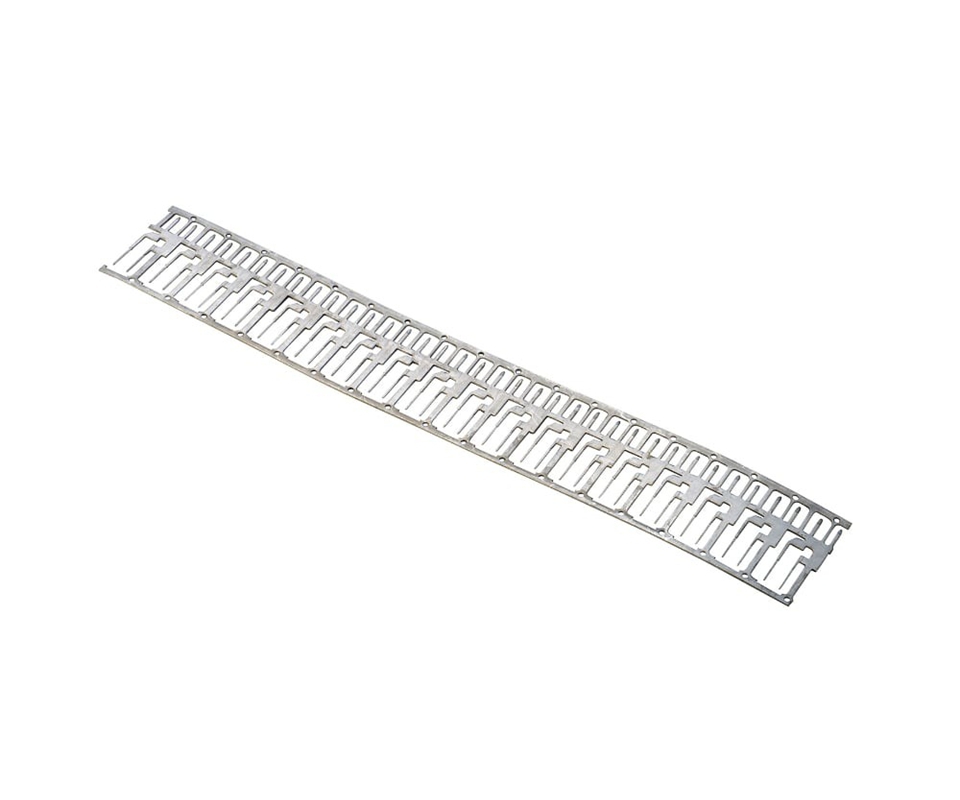
A misfeed — a component arriving 5 milliseconds late or 0.10 mm out of position — results in a missed assembly that the in-die vision system must detect and eject before the terminal reaches the next station.
Feeding Strategies & Sensor Interlock
Three feeding strategies cover the range of secondary component geometries for stamped electrical terminals. Reel-to-reel feeding is used for stamped secondary components — springs, clips, and secondary terminals — that are themselves produced on a progressive die and wound onto reels. The reel feeds into a servo-driven indexer that advances one component pitch per press stroke, synchronized to the press crankshaft angle sensor.
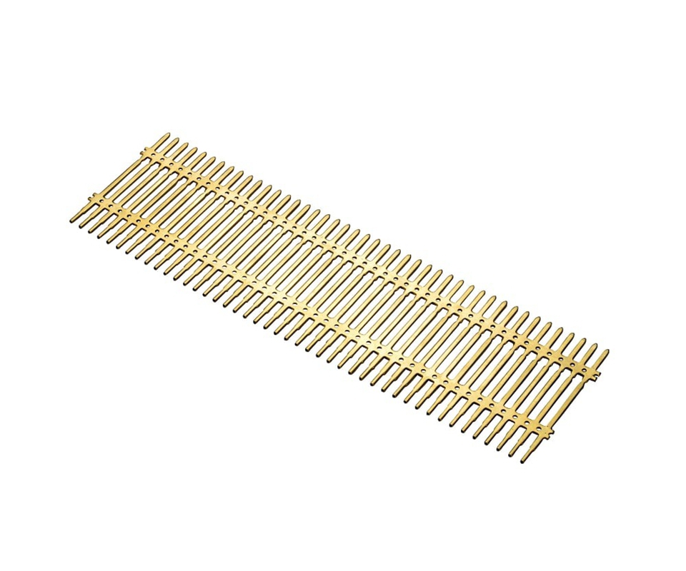
Bowl feeding handles loose components — rivets, pins, and wire forms — delivered through a vibratory bowl that orients and queues parts into a feed track. Magazine feeding handles components too delicate for bowl vibration — pre-assembled sub-components or spring assemblies — loaded into a linear magazine that gravity-feeds or spring-advances one component per cycle.
The feed verification sensor is the safety interlock that prevents the press from cycling on an empty feed track. A fiber-optic sensor at the feed track exit confirms component presence within 10 milliseconds of the staking station engagement. If the sensor detects a missing component, it signals the press control to skip the staking stroke. The press ram retracts without engaging the staking punch, and the un-assembled terminal is ejected at the cutoff station downstream for electrical stamping components in high-speed in-die assembly production.
[CAD Takeaway]: Select the component feeding strategy based on secondary component format — reel-to-reel for stamped sub-components, vibratory bowl for loose hardware, magazine for delicate assemblies — and integrate a fiber-optic presence sensor at the feed track exit with a press-skip signal for misfeed detection within 10 milliseconds of the staking station engagement.
Station Planning & Strip Layout
Station Allocation & Inspection Integration
Each in-die assembly operation consumes 2 to 4 progressive die stations. The first station feeds and positions the secondary component in the terminal body — a locating station that uses spring-loaded fingers or vacuum to hold the component in place. The second station performs the staking, riveting, or coining operation that mechanically locks the component into the terminal.
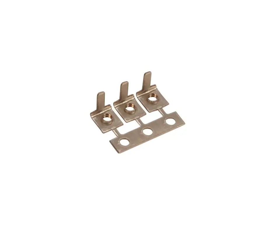
Optional third and fourth stations verify assembly completeness with an in-die vision system and perform a dimensional check on the assembled feature — contact beam height, spring leg position, or rivet head diameter.
3D Clearance Envelope & Press Tonnage
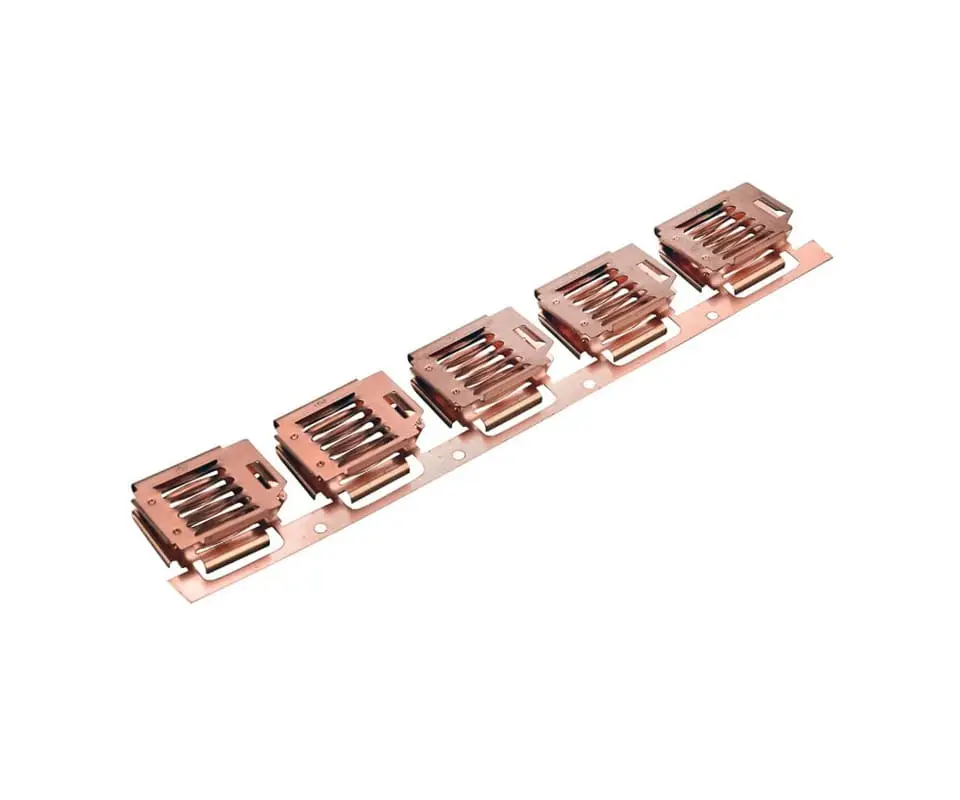
The strip layout must accommodate the physical space that the secondary component occupies after assembly. A terminal with an in-die staked spring clip extends 2.0 to 4.0 mm above the strip plane after assembly. This height must clear the upper die shoe, the strip lifter rails, and the pilot release mechanism. If the assembled component interferes with any die element in the stations downstream of the staking station, the interference damages either the component or the die.
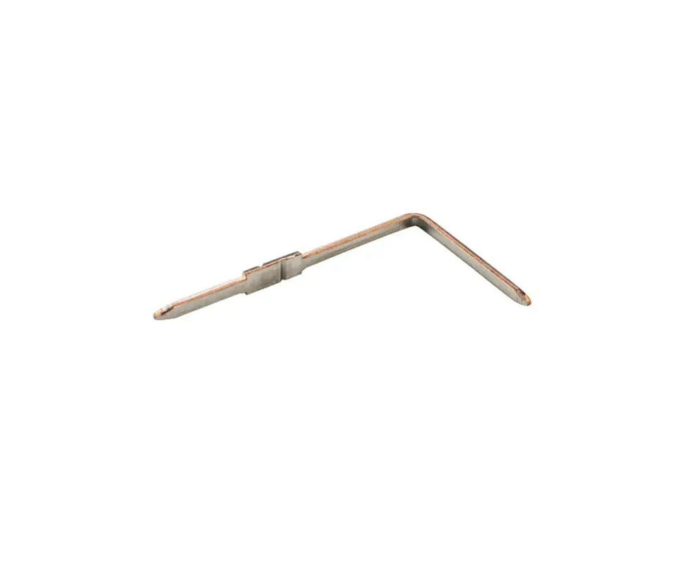
Kravzik‘s strip layout for in-die assembly includes a 3D clearance envelope around the assembled terminal that is verified in the die design CAD before any tool steel is cut for electrical stamping terminals with integrated assembly features.
Press tonnage is the aggregated constraint. A 30-station progressive die with piercing, forming, and staking operations must fit within the press’s tonnage capacity at the bottom of the stroke. The staking station adds approximately 1.0 to 1.5 tons per station to the total tonnage budget — a modest fraction of the 30 to 60 tons required for the piercing and blanking stations at the start of the progression.
[CAD Takeaway]: Allocate 2–4 die stations per in-die assembly operation and verify the assembled component’s 3D clearance envelope against all downstream die elements in the CAD model before die fabrication; size press tonnage for the combined piercing, forming, and staking load at the bottom of the stroke.
Defect Avoidance & Assembly Validation
Common In-Die Assembly Failure Modes
In-die assembly introduces failure modes that standalone progressive die stamping does not have. Missed assembly — the secondary component failed to feed and the staking station cycled on an empty retention slot. Partial assembly — the component is present but not fully seated before staking, producing a weak interlock that fails under vibration.
Staking crack — the staking deformation cracked the terminal body at the slot corner, creating a stress riser that propagates to failure during connector insertion. Component damage — the staking punch contacted the secondary component instead of the terminal body tab, deforming the spring leg or crushing the rivet head.
Vision Inspection & Cross-Section Validation
In-die vision inspection catches missed and partial assemblies before the terminal exits the die. A camera at station 28 — immediately after the staking station at position 26 and the dimensional check station at position 27 — captures an image of the assembled terminal and compares it to a golden template. Missing components, misaligned components, and staking deformations outside the acceptable dimensional envelope trigger an ejection signal.
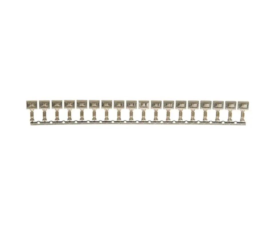
The defective terminal is cut from the carrier strip and ejected into a reject chute at the cutoff station, preventing it from reaching the reel and contaminating the customer’s assembly process for stamped electrical connectors with in-die-assembled components.
First-article assembly validation requires destructive cross-sectioning. Ten consecutive assemblies are mounted in epoxy, cross-sectioned through the staking deformation zone, and examined under a microscope at 50× magnification. The cross-section must show mechanical interlock — terminal body material displaced into the retention slot and contacting the secondary component — with no cracking in the terminal body material at the slot corners.
[CAD Takeaway]: Integrate an in-die vision inspection station immediately after the staking station to detect missed and partial assemblies, and validate the first 10 assemblies by destructive cross-sectioning to confirm mechanical interlock with zero terminal body cracking at the staking deformation zone.
CAD to Production
Separate assembly cells for inserting secondary components into stamped terminals add cost and handling risk that in-die assembly at press speed eliminates. Kravzik’s die design integrates component feeding, staking, inspection, and ejection into the progressive strip layout, delivering finished assemblies at zero downstream labor.
Send your terminal assembly drawing with secondary component specification for an in-die assembly die design including staking mechanics and assembly validation protocol, returned within 3 business days.