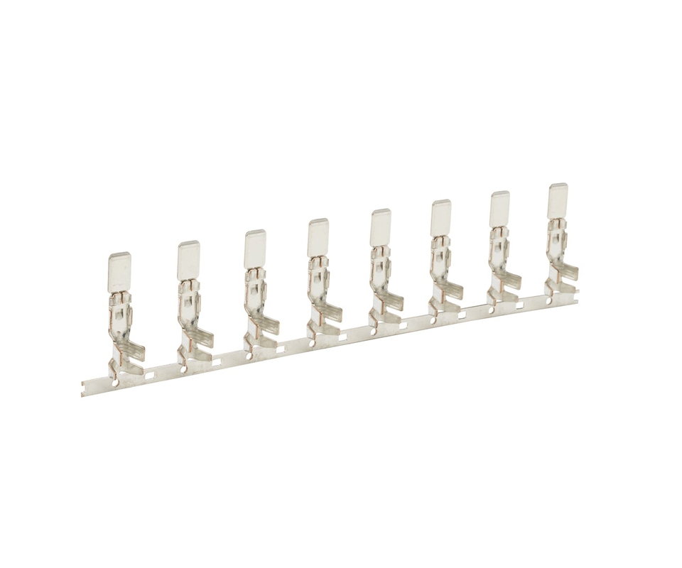
A stamped electrical terminal progressive die stamps 500,000 terminals within the ±0.03 mm tolerance band for the first four production shifts. On shift five, CMM data from the 500,000-stroke sample shows the terminal width has migrated by 0.04 mm — crossing the upper control limit and driving Cpk from 1.45 to 0.92. The batch is quarantined for 100% inspection and the PPAP process capability study is invalidated.
In this analysis, you will learn how to diagnose dimensional drift across three root cause categories — carbide grade and punch wear rate, punch-to-die clearance monitoring and alignment stability, and lubrication delivery at high stroke rates — with corrective maintenance interval adjustments and Cpk trend-based verification.
Read on for the full root cause analysis.
Drift Symptom
Dimensional drift in stamped electrical terminals presents not as a sudden out-of-tolerance condition but as a gradual migration of the measured dimension toward one side of the tolerance band over successive SPC sampling intervals. The X-bar chart shows a positive or negative trend crossing seven consecutive points on the same side of the centerline — the statistical signal for process mean shift under Western Electric Rule 4 — while the R chart remains stable, confirming that the shift is systematic rather than random variation.
The critical insight is that the terminal geometry drifts uniformly across all cavities in the die set but not uniformly across all features. The feature cut by the station with the highest cutting force — typically the profile trim station — drifts fastest because punch wear rate is proportional to the cutting force per unit edge length multiplied by the stroke count.
SPC Pattern Recognition
Plot the Cpk trend over the last 10 sampling intervals at 50,000-stroke increments. A linear Cpk decline with an R² above 0.90 confirms uniform wear-driven drift.
A step change in Cpk at a specific stroke count rather than a gradual decline indicates a tooling event — chipped punch edge, shifted die insert, or lubrication interruption — rather than progressive wear. The corrective action for a step change is immediate die inspection, not a maintenance interval adjustment.
Measure the drifted dimension at all cavities within the die set. Uniform drift across all cavities points to a global variable — punch wear rate, material temper shift, or press ram condition. Cavity-specific drift at only one or two stations indicates localized tooling wear or an insert that has shifted within the die set.
Root Cause Categories
Carbide Grade Selection
Punch wear rate is the primary driver of dimensional drift in progressive die stamping, and carbide grade selection is the single most influential variable controlling wear rate. Standard WC-Co 6% carbide, widely used for stamping C26000 brass terminals, wears at approximately 0.005 mm of punch face material loss per 100,000 strokes at 600 SPM with adequate lubrication. At this rate, the 0.03 mm tolerance band on a terminal width feature is consumed after 600,000 strokes.
WC-Co carbide with 3% cobalt binder and sub-micron grain size reduces the wear rate to 0.002 mm to 0.003 mm per 100,000 strokes on the same material by increasing hardness from 1,600 HV to 1,900 HV and reducing the cobalt binder phase that is preferentially worn by adhesive transfer from the brass strip. The trade-off is approximately 30% lower fracture toughness, which increases the risk of punch chipping if the die set experiences an unintended hard stop from a strip misfeed.
For terminals stamped from C17200 beryllium copper at full-hard temper, the punch wear rate is approximately 2× the rate on copper alloy grades like C26000 brass regardless of carbide grade because the higher yield strength increases the cutting force per unit edge length. Micro-grain WC-Co 3% is mandatory for C17200 terminal production runs exceeding 250,000 pieces to keep the wear rate within a manageable maintenance interval.
Clearance and Alignment
Punch-to-die clearance directly controls dimensional drift because the sheared edge profile — the burnish zone depth, fracture angle, and burr height — shifts as the clearance widens with progressive punch wear. A terminal width specification measured at the burnish-land transition line drifts by approximately 60% of the clearance increase. If the punch wears 0.010 mm and the clearance increases by the same amount, the terminal width at the measurement point drifts by 0.006 mm.
Press ram parallelism is the alignment variable that produces asymmetric drift across the die set. At 60% of rated tonnage on a 400-ton press, the ram deflects by 0.02 mm to 0.05 mm at the center stations compared to the outer stations. Stations near the die center experience wider effective clearance and faster wear acceleration, producing a characteristic V-shaped Cpk pattern when plotted by station position across the die set.
Lubrication Delivery
Lubrication film thickness between the punch flank and the strip material determines whether the wear mechanism is mild abrasive wear or severe adhesive wear. At oil delivery rates above 1.0 mL per minute per station, a continuous hydrodynamic film separates the punch flank from the strip, and wear proceeds by mild abrasion at approximately 0.003 mm to 0.005 mm per 100,000 strokes. At delivery rates below 0.3 mL per minute, the film collapses to boundary lubrication, and adhesive wear accelerates the punch material loss rate to 0.015 mm to 0.020 mm per 100,000 strokes.
The transition from hydrodynamic to boundary lubrication occurs at a specific combination of stroke rate and oil viscosity, not at a fixed delivery rate. At 800 SPM, the oil must be delivered at a minimum of 0.8 mL per minute with a viscosity of 40 cSt at 40°C to maintain hydrodynamic separation. At 400 SPM, the minimum delivery rate drops to 0.4 mL per minute for the same oil because the longer cycle time allows the oil film to re-form between strokes.
Lubrication nozzle positioning is as critical as delivery volume. A nozzle aimed at the strip surface 5 mm before the punch contact point delivers oil to the cutting zone. A nozzle aimed at the punch face delivers oil to the punch body but not the cutting edge — the oil is wiped off by the stripper plate before it reaches the punch-strip interface.
Deep Dive: Explore carbide grade selection for progressive die tooling — including wear rate curves for WC-Co grades from 3% to 10% cobalt binder, micro-grain vs. sub-micron grain size effects on edge retention, and PVD coating options for extended die life on high-strength copper alloys.
Die Wear Trend Analysis: Kravzik’s tooling engineering team analyzes your progressive die wear data — including punch wear measurements at 50,000-stroke intervals, Cpk trend charts, and lubrication delivery parameters — and returns a die-life projection with recommended carbide grade upgrades and maintenance interval optimization. submit your die wear log for a dimensional drift analysis with tool life projections.
Maintenance Adjustments
Non-Destructive Adjustments
These adjustments are implemented at the press line without die removal from the press. For a detailed review of die maintenance protocols, visit progressive die tooling maintenance.
- Increase lubrication delivery rate by 50% at all stations and verify that each nozzle is aimed at the strip surface 3 mm to 5 mm before the punch contact point. Measure dimensional drift after 50,000 strokes at the increased delivery rate. If the drift rate drops by 30% or more, the previous lubrication delivery was below the hydrodynamic threshold.
- Reduce stroke rate by 200 SPM and measure dimensional stability over the next 100,000 strokes. If the Cpk trend line flattens at the lower speed, the punch wear rate at the original speed exceeded the carbide grade’s capability. Reduce the maintenance interval proportional to the original speed until a carbide upgrade can be implemented.
- Verify press ram parallelism with a dial indicator at all four corners of the die set under full tonnage. A ram parallelism deviation exceeding 0.02 mm across the die set diagonal requires press maintenance — the gib adjustment or hydraulic leveling system must be recalibrated to restore uniform clearance distribution.
- Increase SPC sampling frequency from 50,000-stroke intervals to 25,000-stroke intervals when the Cpk trend line projects that the dimension will cross the lower control limit within the next 100,000 strokes. The tighter sampling detects the crossing point with 25,000-stroke resolution instead of 50,000-stroke resolution, reducing the quarantine batch size by half.
Tooling Adjustments
These adjustments require die removal and toolroom intervention.
- Upgrade the punch carbide grade from WC-Co 6% to WC-Co 3% micro-grain for the stations showing the highest wear rate. A full punch-and-die insert set replacement with the upgraded grade extends the maintenance interval from 500,000 strokes to 800,000 strokes on C26000 brass at 600 SPM.
- Apply a PVD TiAlN coating to the punch flanks at stations cutting C17200 beryllium copper. The 3 µm to 5 µm coating with 3,200 HV hardness reduces the adhesive wear component by 40% to 50% and extends the maintenance interval by 200,000 strokes on the harder alloy.
- Install hardened die inserts with a land width of 3.0 mm instead of the standard 1.5 mm at stations where die land wear is the dominant wear mode. The wider land distributes the cutting force across a larger contact area and reduces the local contact pressure at the cutting edge by approximately 40%.
- For die sets where carbide upgrades and coatings do not reduce the drift rate below the acceptable threshold, implement a preventive punch replacement schedule at 80% of the projected strokes-to-failure based on the wear rate trend. Replacing punches before they reach the wear limit eliminates the dimensional drift event entirely and keeps Cpk above 1.33 for the full production run.
For production programs requiring uninterrupted runs exceeding 1 million strokes, contact progressive die tooling engineering to design a die set with quick-change punch inserts that can be swapped at the press line in under 15 minutes without removing the die from the press.
Verification Protocol
Cpk Trend Monitoring
After implementing the corrective action, monitor Cpk at 25,000-stroke intervals for a minimum of 150,000 strokes to establish the new drift rate baseline. Plot the Cpk values on a run chart with the upper control limit set at Cpk 1.33 and the lower control limit at Cpk 1.0. A Cpk trend line with a slope of less than 0.05 Cpk units per 100,000 strokes projects stable production beyond 1 million strokes before crossing the lower control limit. For detailed Cpk verification protocols, refer to our progressive die verification standards.
Conduct a tooling inspection at 100,000 strokes after the adjustment to verify that the punch edge radius, die land condition, and clearance measurements match the predicted values from the wear rate model. A measured wear rate exceeding the predicted rate by more than 30% indicates an unaccounted variable — material temper shift, lubrication degradation, or press condition — that must be identified before the corrective action can be declared effective.
Long-Term Stability
A dimensional drift corrective action is confirmed stable when Cpk remains above 1.33 for three consecutive full production runs without a maintenance intervention. Document the punch wear measurements at the end of each run and compare against the pre-correction wear rate. A sustained reduction of 40% or more in wear rate per 100,000 strokes confirms that the corrective action addressed the dominant wear mechanism.
For new die sets entering production, establish the wear rate baseline during the run-at-rate validation by measuring every punch at 0, 50,000, and 100,000 strokes. This three-point baseline defines the initial wear rate for the specific alloy-temper-lubrication combination and serves as the reference for all future wear rate comparisons on that die set.
Die Wear Life Projection: Kravzik’s tooling engineering team evaluates your progressive die wear data — including carbide grade, SPM, lubrication parameters, and Cpk trend history — and returns a die-life projection with ranked recommendations for carbide grade, coating, and maintenance interval optimization to extend production runs above 1 million strokes. submit your die wear data for a dimensional drift analysis with carbine upgrade recommendations.
Fix & Verify
Re-grinding punches without accounting for cumulative length loss can cause forming stations to bottom out before trim stations, producing undersized features across every cavity. Kravzik’s progressive die maintenance tracks every punch’s grinding history, calculates re-grind depth to preserve forming-to-cutting relationships, and returns die sets with post-service CMM verification confirming Cpk above 1.33.
Send your die wear log for a complete dimensional drift analysis with carbide grade evaluation, lubrication optimization, and maintenance interval recommendations, delivered within 48 hours.