A stamped retention lance that engages at 0.15 mm instead of the design target of 0.30 mm (due to a 2° lance angle variation) passes the insertion force check but releases the terminal under the first vibration pulse on the vehicle assembly line. The terminal moves rearward by 0.5–2.0 mm, the contact interface opens, and a fully assembled wiring harness turns into a dead circuit that requires hours of teardown diagnosis.
In this reference, you will find the lance geometry fix, the tolerance stack limits, and the Cpk > 1.33 validation per EIA-364-29 that eliminate terminal backout failure.
Read the full fix.
The Failure – What Breaks & What It Costs
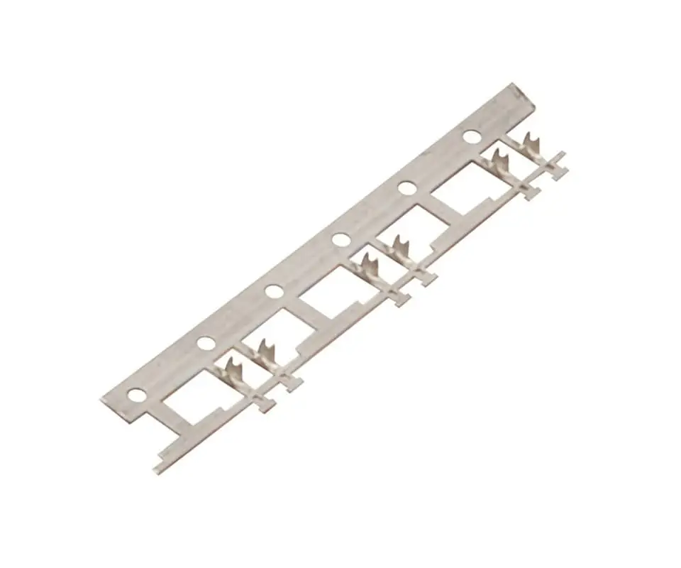
The stamped retention lance is a cantilever beam formed into the terminal body during progressive stamping. It engages a shoulder or step in the connector housing cavity, preventing rearward movement. If the lance angle is off by 2 degrees, the engagement depth drops from 0.3 mm to 0.15 mm, and retention force drops from 80N to below 40N, creating a high risk of failure during assembly or operation.
The Retention Lance – Single-Point Failure
One backed-out terminal in a 42-pin engine ECU connector causes a no-start condition, with diagnostic costs reaching $400-800 per incident including ECU swaps and harness continuity checks. A 0.1% backout rate on 100,000 connectors per year equates to 100 field failures and $40,000-80,000 in warranty claims. Preventing this requires rigorous control over the progressive die tooling used to form the retention features.
[Spec Takeaway]: Demand retention lance engagement geometry verification at Cpk over 1.33 on every production lot – lance angle, engagement depth, and lance-to-housing clearance must be measured per EIA-364-29.
The Root Cause – The Hidden Variable
Terminal backout is almost never a single root cause, but rather a tolerance stack failure where terminal and housing cavity dimensions drift within their individual tolerances. In modern USCAR-2-class connectors, the primary retention lance is complemented by a Terminal Position Assurance (TPA) feature.
However, if the primary lance engagement depth is below 0.20 mm, the TPA interlock may still permit rearward movement under vibration. The true root cause is often the stamper’s failure to validate the assembled retention force including the TPA interlocking state.
Tolerance Stack – The Domino Effect No One Owns
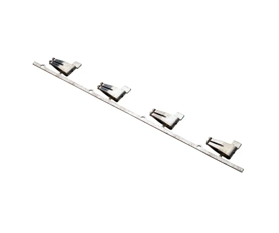
The three-variable tolerance stack involves the terminal lance height (tolerance ±0.03 mm), the housing cavity shoulder height (tolerance ±0.05 mm), and the lance spring-back angle (tolerance ±1.5 degrees). A worst-case stack where the lance is low, the cavity is high, and spring-back is excessive can reduce engagement depth from a 0.30 mm design intent to just 0.15 mm, causing a 50% drop in retention force.
What most suppliers get wrong is measuring terminal dimensions on a granite surface plate and signing off without ever functionalizing the assembly. A terminal and housing can both be “within tolerance” individually but fail to produce the required retention force when mated. True reliability comes from measuring the assembled function rather than just the constituent parts.
[Spec Takeaway]: Validate assembled retention force, not individual component dimensions – a terminal and housing that both pass dimensional inspection can produce engaged retention force below 60N when assembled.
Die Wear – The Progressive Failure No One Tracks
The retention lance is formed in the final progressive die stations using wipe-bending or coining. As the forming punch wears, the root radius increases, changing the springback angle by up to 1.0 degree per 50,000 strokes, while die clearance wear produces burrs at the lance tip. After 300,000 strokes, the combined effect reduces engagement depth and introduces “false engagement” risk – where a burr catches on the housing cavity ramp, producing a tactile click that mimics correct locking when the lance tip has not yet reached the shoulder.
Die wear monitoring requires measuring lance angle, engagement depth, and burr height on consecutive parts at 50,000-stroke intervals. Plotting these on an X-bar R chart allows for resharpening when the trend reaches the control limit – before rejectable parts are produced. Any burr height exceeding 0.05 mm should trigger an immediate die inspection regardless of other measurements.
[Spec Takeaway]: Require lance geometry measurement at 50,000-stroke intervals with X-bar R chart trending – resharpen the lance forming station when the trend line reaches the 2-sigma warning limit, not the 3-sigma reject limit.
The Fix – Parameters Your Supplier Must Meet
Terminal backout is prevented by controlling three parameters: lance engagement geometry, assembled retention force, and lance forming die condition. This requires a supplier capable of stamped terminal production with in-process measurement rather than end-of-line sampling. The following fix protocol defines the mandatory acceptance criteria.
Retention Force Fix Protocol
The three-element fix protocol includes: (1) lance geometry measured by a vision system at 50,000-stroke intervals; (2) assembled retention force measured on 5 terminals per cavity every 2 hours per EIA-364-29; and (3) lance forming station punch and die insert replacement at 300,000 strokes. This proactive approach captures drift in lance angle that standard shift-based comparator checks would miss.

| Parameter | Minimum Threshold | Measurement Method | Industry Standard |
|---|---|---|---|
| Lance Angle | ±1.5 degrees of nominal | Vision system at 50x | EIA-364-29 |
| Engagement Depth | ≥ 0.25 mm (primary lance) | Optical comparator section view | USCAR-2 §5.3.4 |
| Assembled Retention Force | ≥ 60N (with TPA engaged) | Load cell per EIA-364-29 | EIA-364-29 |
| Burr Height | ≤ 0.05 mm at lance tip | Stereomicroscope at 20x | USCAR-2 |
[Spec Takeaway]: Demand assembled retention force above 60N per EIA-364-29 measured on 5 terminals per cavity per 2-hour interval – reject the production lot if any single measurement falls below 50N or if Cpk drops below 1.33.
Prevention – Supplier Accountability Protocol
The supplier accountability protocol starts at the PPAP submission and continues through every production lot. The goal is to validate that the terminal, the housing, and the assembly process produce consistent retention force – not just consistent component dimensions. This must be integrated into the supplier’s quality management system to ensure long-term compliance.
PPAP & Production Validation Gates
PPAP Level 3 requirements must include a capability study on lance geometry and assembled retention force (n=125, Cpk over 1.33) using production-intent housings. Furthermore, a die wear study must demonstrate lance geometry stability over 300,000 strokes, and retention force must be validated after environmental aging (1000h at max operating temp) to ensure the design’s environmental durability.
Production monitoring continues with vision-based lance geometry checks at 50,000-stroke intervals and assembled retention force measurements every 2 hours. A hard stop for lance station punch and die replacement at the 300,000-stroke preventive maintenance trigger prevents the progressive degradation that leads to field backout failures.
[Spec Takeaway]: Require PPAP submission with assembled retention force Cpk over 1.33 on 125 production-intent samples – dimensional-only PPAPs are insufficient for retention-critical terminals per USCAR-2 Section 5.3.4.
Data to Spec: The Stamped Terminal Supplier Mandate
You approved the terminal supplier’s PPAP six months ago with a dimensional report showing all lance dimensions within tolerance at a Cpk over 1.50. Now the harness assembly line is rejecting 3 connectors per 1,000 for backout – the operator feels the terminal push back during insertion force testing.
Teardown reveals a lance engagement depth of 0.12 mm, which is 60% below the design intent. The PPAP missed assembled retention force validation. The dimensions were in spec, but the function failed because the housing was at its high limit and the lance angle had drifted.
Kravzik validates assembled retention force on production-intent connector housings at PPAP and at 2-hour intervals during production per EIA-364-29. Our lance forming stations run on a preventive maintenance schedule: vision geometry check every 50,000 strokes with real-time X-bar R chart trending, and punch/die insert replacement at 300,000 strokes. This protocol has produced uninterrupted returns-free production runs of 2 million terminals with zero backout field failures.
Still relying on dimensional inspection to prevent terminal backout? Send us your terminal print for a retention force risk assessment. Kravzik returns a tolerance stack analysis, a lance geometry capability recommendation, and a production monitoring protocol within 48 hours.