An intermittent contact that measures 3 mΩ at IQC but spikes above 50 mΩ after 40,000 miles on the road is the most expensive failure mode to diagnose. It passes the shaker table and thermal cycling at the Tier-1 supplier but manifests unpredictably in the field, consuming weeks of warranty investigation before the root cause is identified.
In this reference, you will discover the LLCR diagnostic protocol, the bend apex plating thickness threshold, and the EIA-364-23 validation fix that detect plating porosity and oxide accumulation before they cause field returns.
Read the full fix.
The Failure – What Breaks & What It Costs
Three distinct mechanisms produce the same intermittent high-resistance symptom: plating porosity exposes the copper substrate to corrosion, oxide film buildup thickens the SnO2 layer beyond the contact force’s penetration limit, and particulate contamination lodges at the interface. These sub-microscopic defects create a high-resistance barrier that disrupts the signal path, particularly in low-voltage sensor circuits where electrical breakdown of the film is impossible.
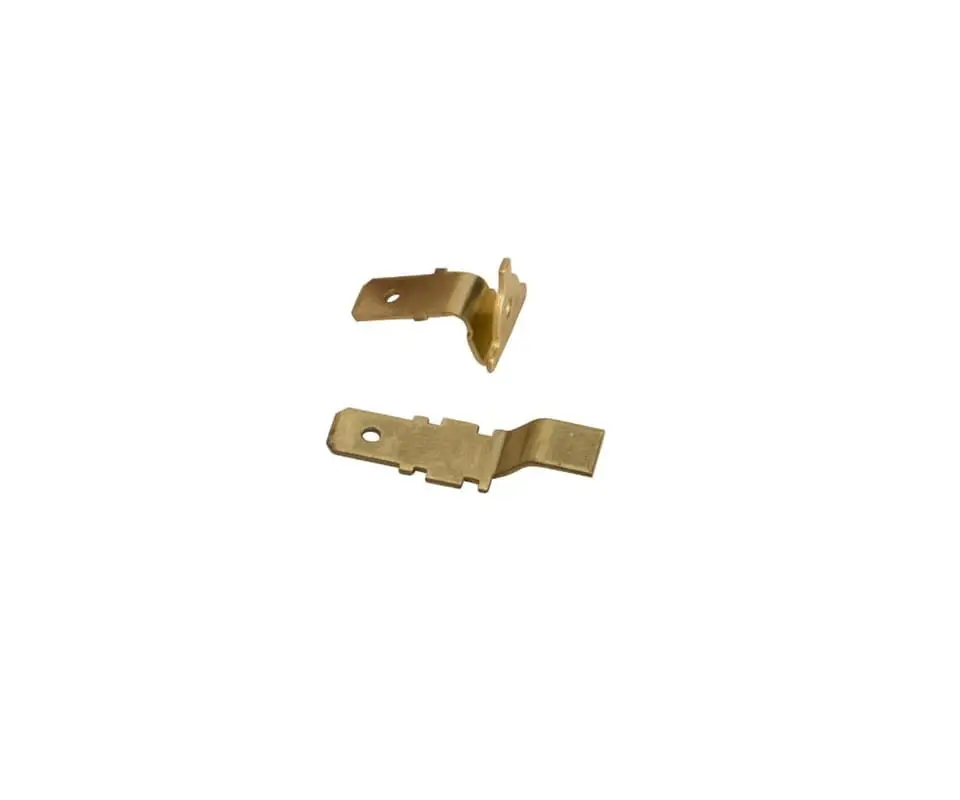
Three Root Mechanisms, One Symptom
The business impact of a single intermittent contact in a 64-pin ECU connector is massive, often triggering a chain of costly events including ECU replacement and extensive labor hours. Since the contact often passes standard continuity tests performed by dealer technicians, the average diagnostic cost per event reaches $1,200-2,400. To detect these faults during the stamped terminal production phase, Low-Level Contact Resistance (LLCR) measurement at below 20 mV open-circuit voltage per EIA-364-23 is mandatory.
[Spec Takeaway]: Demand Low-Level Contact Resistance (LLCR) measurement at below 20 mV open-circuit voltage per EIA-364-23 – standard 4-wire measurement at 1A masks film resistance that only appears at signal-level voltages.
The Root Cause – The Hidden Variable
Intermittent contact resistance is rarely a single-variable root cause, but rather a chain of conditions starting with a plating defect like a pore or thin spot. This allows oxide formation at the substrate interface, which thermal cycling then opens and closes. The final variable is the connector’s vibration profile, which determines whether this intermittent state manifests during vehicle operation or remains dormant during laboratory testing.
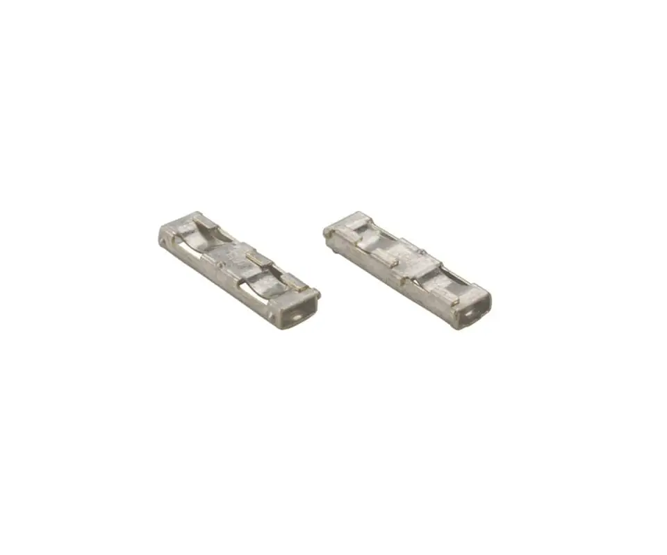
Plating Porosity – The Sub-Surface Defect
Tin plating on copper alloy terminals requires a minimum 2.5 µm thickness per ASTM B545 to keep porosity below 5 pores per square millimetre. At 1.5 µm, porosity spikes to 15-25 pores, allowing copper substrate corrosion products (Cu2O) to grow laterally under the tin layer in a process called corrosion creep. A nickel barrier underplate of 1.27 µm minimum between the substrate and top-coat blocks copper diffusion and retards this lateral creep by 5-10x, serving as the primary defense in automotive terminals.

What most suppliers get wrong is measuring plating thickness on a flat coupon rather than at the contact beam bend apex where current density is lowest and the plating is thinnest. A terminal measuring 3.0 µm at the flat shank may measure just 1.2 µm at the bend apex. Porosity should be validated through 10x stereomicroscope inspection after 24h salt spray exposure per ASTM B117, counting dark spots in the 2 mm contact zone to ensure they remain below 2 pores per square millimetre.
[Spec Takeaway]: Measure tin plating thickness at the contact beam bend apex, not the flat shank – reject any terminal where the bend apex thickness falls below 2.0 µm regardless of flat-area measurement per ASTM B545.
The LLCR Blind Spot – Why Standard 4-Wire Testing Lies
Standard contact resistance measurement at 100 mA (IEC 60512-2 Test 2a) applies enough voltage to electrically break down thin oxide films through A-fritting – thermally assisted field emission across the oxide barrier. This masks the intermittent condition entirely. The true resistance is only revealed under Dry Circuit Conditions, where test voltage stays below 20 mV and current below 100 mA per EIA-364-23, preventing any fritting or micro-arcing from puncturing the film.
A terminal with 15 nm SnO2 might measure 3.5 milliohms at 100 mA because the film is broken down by fritting, but it could measure 450 milliohms at 10 mV with the film intact. This latter value represents the actual signal-level operating condition in a sensor circuit. LLCR per EIA-364-23 is the definitive diagnostic method for these signal-level contacts to ensure they will function reliably in the field.
[Spec Takeaway]: Use LLCR measurement at below 20 mV per EIA-364-23 for all signal-level terminals – reject any contact where LLCR exceeds 10 milliohms after 1000h thermal aging, regardless of the 100 mA contact resistance reading.
The Fix – Parameters Your Supplier Must Meet
Intermittent contact resistance is eliminated by controlling plating thickness at the contact interface, verifying low porosity, and measuring LLCR at signal-level voltage after thermal aging. This requires a supplier with a high-performance in-house tin plating line and the specialized instrumentation needed for dry circuit validation. The following table defines the mandatory pass/fail boundary.
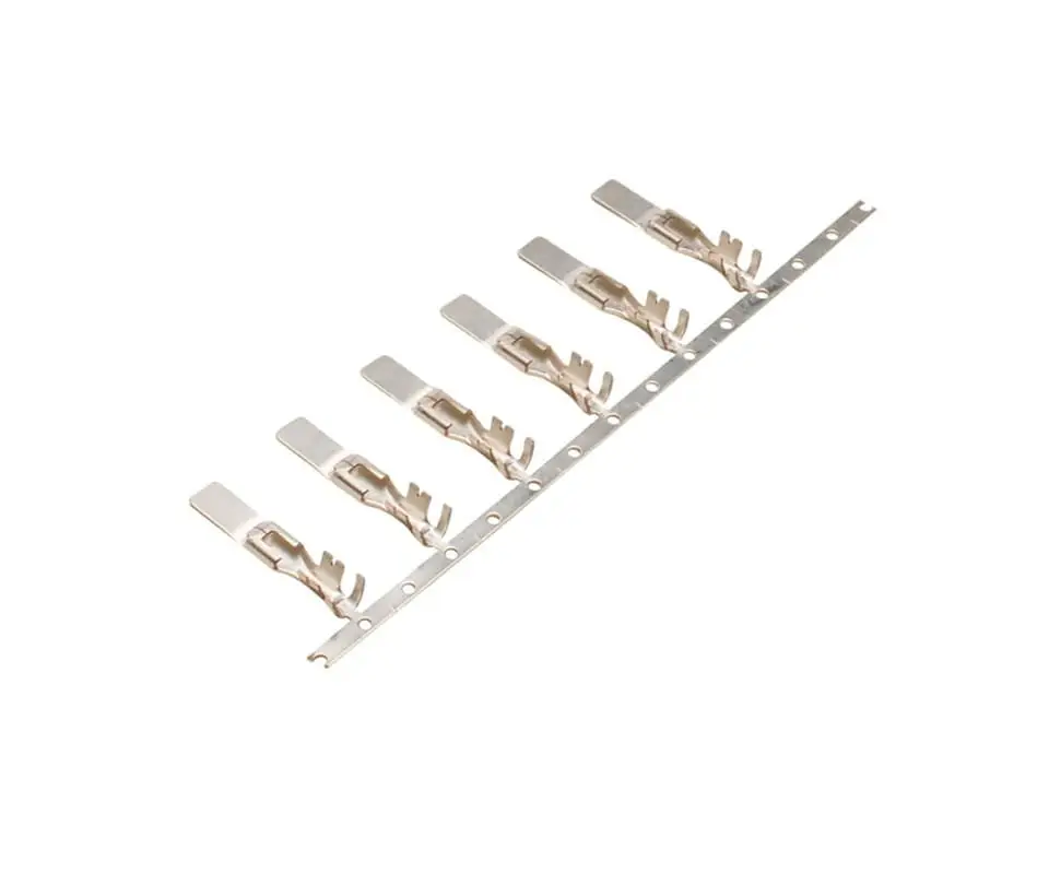
| Parameter | Minimum Threshold | Measurement Method | Industry Standard |
|---|---|---|---|
| Tin Plating Thickness (bend apex) | ≥ 2.5 µm | XRF on bend radius | ASTM B545 |
| Nickel Barrier Underplate | ≥ 1.27 µm | XRF cross-section | USCAR-2 |
| Porosity Rate | ≤ 2 pores / mm² after 24h salt spray | Stereomicroscope at 10x per ASTM B117 | ASTM B545 |
| LLCR at < 20 mV | ≤ 10 milliohm after 1000h aging | 4-wire Kelvin per EIA-364-23 | EIA-364-23 |
[Spec Takeaway]: Demand LLCR below 10 milliohms at below 20 mV open-circuit voltage after 1000h thermal aging per EIA-364-23 – the standard 100 mA contact resistance test is insufficient for signal-level terminal validation.
Prevention – Supplier Accountability Protocol
The accountability protocol starts at the plating process control plan and extends through production lot LLCR validation. The goal is to eliminate the conditions that permit oxide film buildup at the contact interface rather than trying to catch intermittents at end-of-line testing where they frequently escape detection. This protocol must be hard-coded into the supplier’s quality management system.
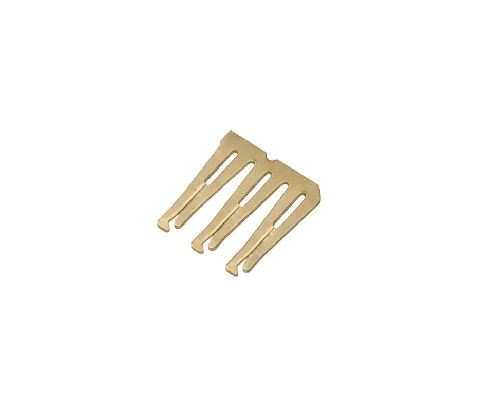
Plating Process Control & PPAP Gates
Plating process control requires XRF thickness measurement at three positions per terminal strip (center, edge, and bend zone) at 30-minute intervals. Salt spray porosity tests per ASTM B117 must be performed on 5 terminals per shift, and LLCR validation per EIA-364-23 is required for both the PPAP submission (n=32) and every production lot (n=5). This multi-layered defense ensures sub-surface corrosion never reaches critical levels.
PPAP requirements must include a plating thickness capability study at the bend apex with a Cpk over 1.33, a porosity rate below 2 pores per square millimetre, and LLCR below 10 milliohms after 1000h thermal aging. A detailed plating bath chemistry control plan with replenishment triggers is also necessary to prevent the process drift that causes thin plating and high porosity.
[Spec Takeaway]: Require plating thickness XRF measurement at the contact beam bend apex at 30-minute production intervals with Cpk over 1.33 – flat-shank-only thickness data is insufficient for contact-critical terminals.
Data to Spec: The Stamped Terminal Supplier Mandate
You approved the terminal supplier’s plating C of C showing tin thickness of 3.2 µm and contact resistance of 3.5 milliohms at IQC. Six months later, field data shows 12 throttle position sensor DTCs across 8,000 vehicles, yet the connector passes the dealer’s continuity test every time.
Teardown reveals LLCR at 10 mV measures 450 milliohms on terminal #3, while SEM cross-sections show tin thickness at the bend apex is only 1.1 µm. The original measurements were taken on the flat shank at 100 mA – masking the true failure.
Kravzik measures tin plating thickness by XRF at the contact beam bend apex at 30-minute production intervals, not on a flat coupon. Our PPAP submission includes porosity rate after 24h ASTM B117 salt spray and LLCR at below 20 mV per EIA-364-23 after 1000h thermal aging. This protocol catches the sub-surface corrosion path that standard 4-wire contact resistance measurement at 100 mA masks, ensuring signal-level reliability in the most demanding environments.
Still trusting contact resistance data that was measured at 100 mA on flat-shank plating coupons? Send us your terminal print for an LLCR risk assessment. Kravzik returns a plating thickness profile at the contact interface, porosity analysis, and an LLCR validation protocol within 48 hours.