A stamped terminal that passes the dimensional layout review fails the connector qualification test at thermal cycle 800. The failure mode changes across suppliers, alloy grades, and connector architectures. The root cause – a design parameter that was never checked at the drawing review – does not.
In this guide, you will discover the 6 most common failure modes in stamped electrical terminals – what each failure looks like in teardown, the design parameter that controls it, and the verification check that prevents it from reaching production.
Read the breakdown.
Spring Force Relaxation
Key Advantage
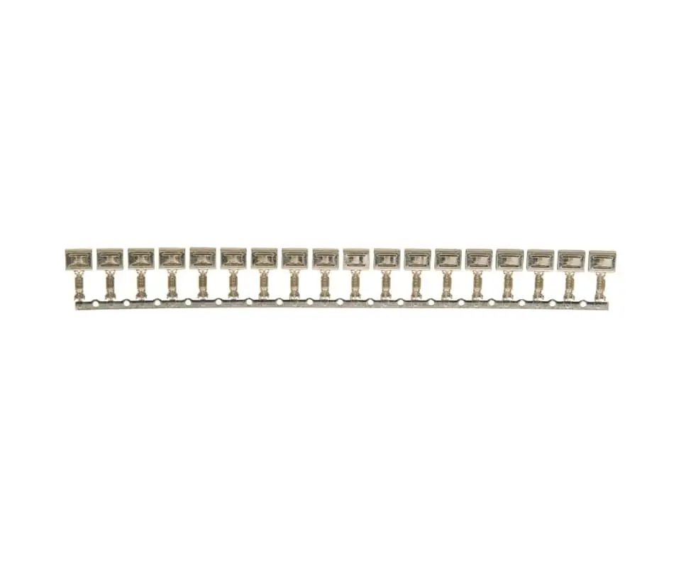
Spring force relaxation is the progressive loss of contact normal force when the terminal beam is held at constant deflection under elevated temperature. The failure is invisible at room-temperature IQC – force readings are nominal – but after 1000h at 105°C the contact force drops below the 2.0N threshold for tin-plated contacts per IEC 60512-2. This is a primary concern in stamped terminal production for automotive applications.
Best Used For
Any tin-plated terminal in a sealed connector operating above 80°C ambient requires specific alloy selection. C17200 retains 95% at 150°C. C51000 retains 85% at 125°C.
C11000 and Brass 260 must be excluded from contact beam applications above 80°C to prevent intermittent contact and resistance spikes.
The Trade-off
The higher the alloy’s relaxation resistance, the higher the material cost. C17200 costs 4–6x more than C11000 per kilogram.
The over-spec penalty is cost. The under-spec penalty is field failure and warranty claims that can cripple a product launch.
Fretting Corrosion
Key Advantage
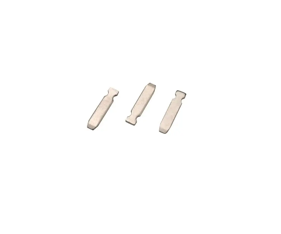
Fretting corrosion occurs when vibration or thermal expansion produces 25–75 µm relative movement at the tin-to-tin contact interface. Each cycle strips the protective oxide layer, debris accumulates, and contact resistance rises from milliohm-level to above 10 milliohms within 10,000 cycles. Maintaining a high-standard quality management system is essential to detect this during qualification.
Best Used For
Terminals in engine-bay and chassis-mounted connectors exposed to vibration per USCAR-2 are most vulnerable. The design parameters: contact normal force above 2.0N at max operating temperature, terminal-to-housing lateral clearance below 100 µm, and contact lubricant (like PFPE-based grease) at 5–10 µg per contact.
The Trade-off
Tighter housing cavity clearances increase tooling cost and assembly insertion force. Every 25 µm reduction in lateral clearance below 150 µm adds approximately 10–15% to the connector housing mold precision requirement.
Terminal Backout
Key Advantage
Terminal backout occurs when the retention lance disengages from the connector housing cavity, allowing the terminal to move rearward by 0.5–2.0 mm. The contact interface opens and the circuit goes dead – instantly, without warning, and often intermittently as the terminal re-engages under vibration. This failure is a critical focus for progressive die tooling optimization.
Best Used For
All terminals in multi-pin connectors where a single backout disables a critical function (ECU, airbag, ABS) require redundant protection. The design parameters: lance engagement depth 0.25–0.35 mm with Cpk over 1.33, lance angle within ±1.5 degrees of nominal, and assembled retention force above 60N per EIA-364-29.
The Trade-off
Deeper lance engagement conflicts with connector miniaturization. Each 0.05 mm increase in engagement depth adds approximately 0.2 mm to connector pitch – the difference between a 2.54 mm pitch and a 2.74 mm pitch that may not fit the PCB footprint.
Intermittent Contact
Key Advantage
Intermittent contact is the most difficult failure mode to diagnose because it appears and disappears. At 100 mA test current (standard contact resistance measurement per IEC 60512-2), the contact measures 3.5 milliohms.
At 10 mV – the actual signal-level voltage in a sensor circuit – it measures 450 milliohms because the oxide film is intact at low voltage. This diagnosis requires specialized in-house plating capabilities.

Best Used For
Signal-level terminals in sensor, communication, and low-voltage circuits where the operating voltage is below the oxide breakdown threshold of approximately 100 mV. The design parameters: tin plating thickness at the bend apex above 2.5 µm, porosity below 2 pores per square millimetre, and LLCR below 10 milliohms at below 20 mV per EIA-364-23.
The Trade-off
LLCR testing at below 20 mV is not part of standard connector qualification and adds 2–3 hours to the test sequence. The cost of skipping it is intermittent field failures that pass every standard continuity test at the dealership.
Fatigue Fracture
Key Advantage
Fatigue fracture occurs at the contact beam bend root after repeated insertion-extraction cycles. Unlike the other five failure modes, fatigue fracture is binary – the beam snaps, the circuit opens permanently, and the failure is immediately obvious.
C11000 fatigues at 60 MPa at 10⁷ cycles. C17200 fatigues at 210 MPa.
Best Used For
Terminals in connectors rated for above 5,000 mating cycles (service connectors, test fixtures, battery connectors) require fatigue-resistant design. The design parameters: alloy fatigue limit at operating temperature, bend radius above alloy minimum, and coining at 5–15% thickness for C51000 and C17200.
The Trade-off
Increasing the bend radius to improve fatigue life increases the terminal’s overall height, conflicting with low-profile connector requirements. A 0.05 mm increase in bend radius can add 0.15 mm to the terminal’s z-height after springback.
Plating Adhesion Loss
Key Advantage
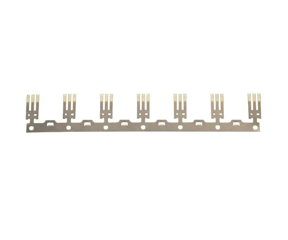
Plating adhesion loss occurs when the tin or silver top-coat delaminates from the copper alloy substrate under mechanical stress during connector mating. The delaminated plating folds back, exposing the substrate to galvanic corrosion and creating a high-resistance path at the exposed edge. This requires a robust in-house plating line with precise bath control.
Best Used For
Terminals with tight bend radii below 1.5t and C17200 or C51000 substrates require a barrier layer. The design parameters: nickel strike layer of 1.0–2.0 µm before tin top-coat for C17200, 0.5–1.0 µm for C51000, and cross-hatch adhesion rating of 5B per ASTM D3359 after bend testing.
The Trade-off
The nickel strike layer adds approximately 10–15% to the plating cost per reel and adds one plating bath station to the production line. The cost of skipping it: delamination at the first connector mating cycle.
Common Failure Modes Summary
| Failure Mode | Appearance at Teardown | Root Design Parameter | Detection Method | Design Fix | Qualification Standard |
|---|---|---|---|---|---|
| Spring Force Relaxation | Gapped contact beam | Alloy selection | Thermal aging 1000h | Upgrade to C17200 | IEC 60512-2 |
| Fretting Corrosion | Black oxide debris | Lateral clearance | Vibration test | Reduce clearance < 100 µm | USCAR-2 |
| Terminal Backout | Terminal pushed rearward | Lance engagement | Retention force test | Increase engagement depth | EIA-364-29 |
| Intermittent Contact | Clean contact (oxide film) | Plating porosity | LLCR at < 20 mV | Increase tin > 2.5 µm | EIA-364-23 |
| Fatigue Fracture | Fractured beam root | Bend radius | Mating cycle test | Increase R/t ratio | EIA-364-09 |
| Plating Adhesion Loss | Flaked/peeled plating | Nickel strike layer | Cross-hatch test | Add 1.27 µm Nickel | ASTM D3359 |
Your Quick Takeaway
You signed the terminal PPAP six months ago – dimensional report clean, material certs in order, first-article inspection passed. Now the connector qualification test shows three failures at thermal cycle 600: terminal #3 contact resistance above 15 milliohms, terminal #7 spring force below 2.0N, terminal #12 plating delamination at the bend apex. Three different failure modes, one common root cause: the design review checklist checked only what was on the print, not what governs in-service behavior.
Kravzik reviews terminal designs against all 6 failure modes before the first strip enters the press. Our DFM assessment checks alloy relaxation resistance at operating temperature, contact force derating, fretting clearance, LLCR signal-level performance, and plating adhesion on the actual bend radius – not a flat coupon.
Checking your next terminal design against all 6 failure modes before the connector qualification test finds them? Send us your terminal print for a failure mode risk assessment. Kravzik returns a design review checklist with alloy recommendations, plating protocol, and tolerance stack clearance verification within 48 hours.