A single micro-burr on a contact beam —invisible to the naked eye —can spike contact resistance from 5 mΩ to over 50 mΩ. When that terminal carries 15 A continuous in an EV battery management system, the I²R heating at the burr tip raises the local temperature by 40 °C above ambient, accelerates oxidation at the mating interface, and eventually triggers a thermal runaway chain that forces a six-figure sorting campaign at the Tier-1 level.
In this guide, you will learn the full engineering landscape for specifying stamped electrical terminals with production-grade precision: alloy selection against normal force windows, tolerance stack-up control across multi-bend geometries, plating strategy for environmental durability, and the latent failure modes that separate a reliable production program from a field-recall disaster.
Read on for the full guide.
Definition & Boundaries
A stamped electrical terminal is a thin-gauge metal contact produced by progressive die stamping from copper alloy strip stock. Its core function is threefold: establish a gas-tight electrical contact at the mating interface, maintain a defined normal force window across the full service life, and provide a reliable termination point for the wire, busbar, or PCB pad. Material thickness ranges from 0.10 mm for micro-signal contacts in consumer electronics to 1.20 mm for high-current power terminals in stamped electrical terminals used in EV battery interconnects and industrial power distribution.
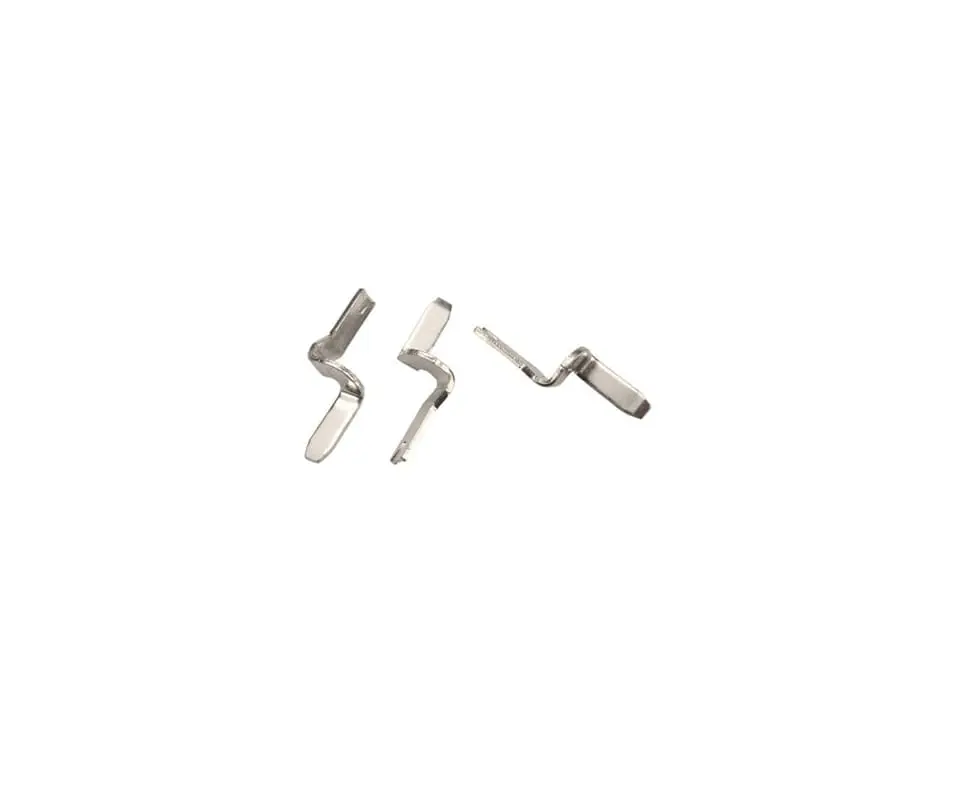
Stamped Terminals vs. Machined Contacts
Sourcing managers frequently face the decision between specifying stamped electrical contacts and turning to screw-machined or CNC Swiss-type contacts. The choice is not a cost-versus-quality trade-off. It is a geometry-versus-volume decision where each process owns legitimate engineering niches.
Understanding where each architecture wins prevents the most common sourcing error: over-specifying a machined contact for a 500,000-piece annual program and burning tooling budget that progressive die stamping could have amortized inside 12 months.
Process Profile —Stamped Terminals
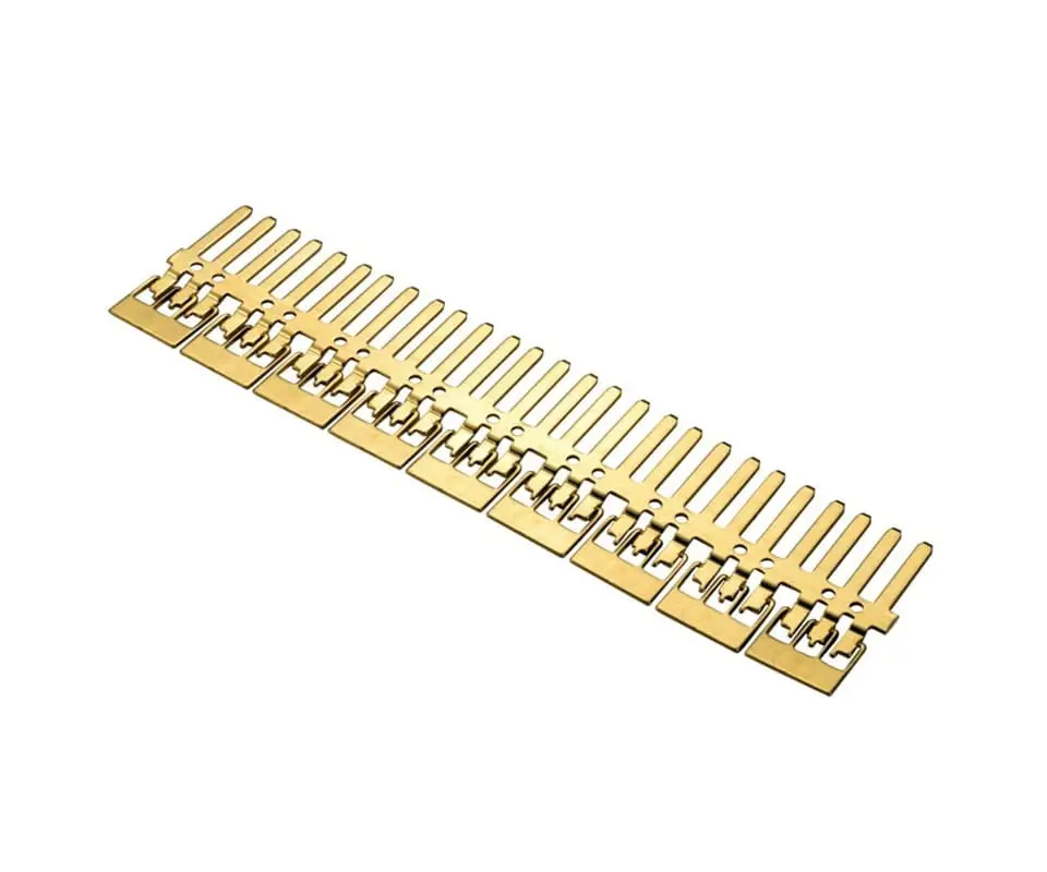
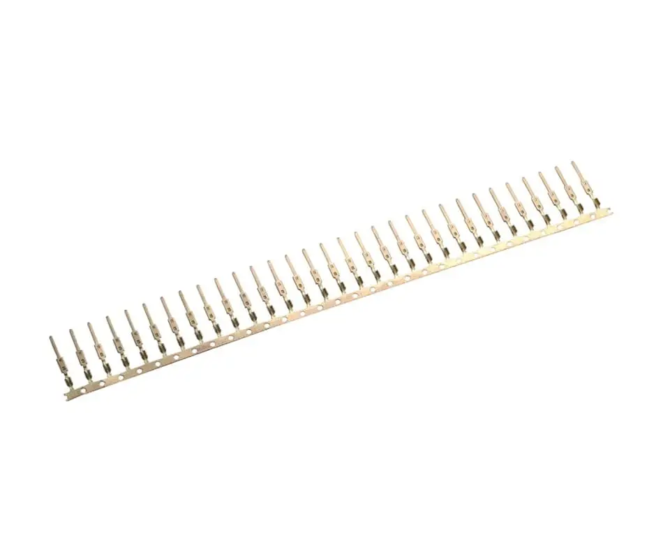
Progressive die stamping produces contacts at speeds exceeding 800 SPM on high-speed presses. The strip is fed from coil stock through a sequence of 20 to 60 stations —piercing, blanking, forming, coining, and cutoff —all within a single die set. The breakeven volume typically falls between 50,000 and 150,000 pieces annually depending on die complexity and strip width.
Kravzik‘s high-speed progressive die stamping lines maintain punch-to-die clearances at 5% to 8% of material thickness, a window that directly governs burr height on the final contact edge and determines whether the terminal passes or fails contact resistance at the 18-month mark.
Key Advantage —Unit Economics at Volume
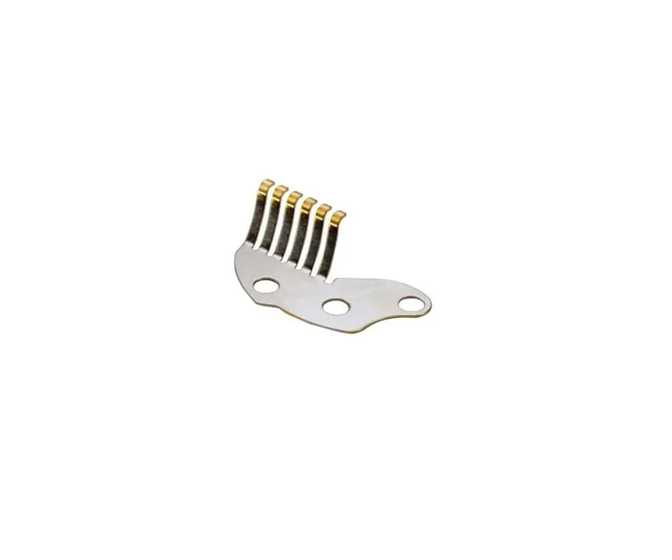
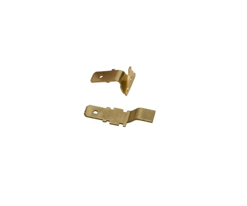
The dominant advantage of stamped terminals is per-part cost at volume —typically 60% to 80% lower than equivalent machined contacts above 100,000 pieces annually. The second advantage is cross-sectional design flexibility: a stamped terminal can transition from a 0.64 mm square wire pin to a 6.0 mm wide blade within a single part, something impossible in a turned component. This capability is critical for custom metal terminals that must mate with both a PCB through-hole and a blade-style header in the same connector system.
The third advantage is process scalability: once the progressive die is validated, adding production capacity requires only additional press time rather than additional machine setups. A 16-cavity die running at 800 SPM produces 768,000 terminals per eight-hour shift —output that would require a bank of 40 Swiss-type lathes running simultaneously. For programs scaling from 100,000 to 5 million annual pieces, this capital-to-throughput ratio makes stamping the only economically viable process at production volumes.
Where Machined Contacts Still Win
Machined contacts own the sub-±0.005 mm tolerance envelope and full 3D geometry space that progressive dies cannot produce:
- Cross-drilled holes
- Internal threads
- Undercuts
- Stepped diameters
They also carry zero tooling barrier: a Swiss-type lathe setup requires only a collet, guide bushing, and CAM program, representing setup costs measured in hundreds of dollars. For prototyping runs under 500 pieces or annual volumes below 5,000 units, machining avoids the tooling amortization burden entirely.
The trade-off is per-part cost: $0.15 to $1.50 for machined contacts versus $0.002 to $0.05 for stamped equivalents at volume, with the breakeven typically landing between 10,000 and 50,000 annual units depending on geometry complexity and material grade.
Stamped terminals also carry an inherent directional bias. The rolling direction of the base strip creates anisotropic mechanical properties. The normal force in the mating axis can differ from the forming axis by 5% to 10%.
This is manageable through FEA simulation and grain-direction-aware strip layout, but it requires upfront engineering investment. A machined contact, by contrast, is isotropic, making it the default choice for ultra-high-reliability military circular connectors where volume is low and failure is not an option. For electrical stamping parts in high-volume automotive and industrial applications, the anisotropic effect is well-characterized and compensated during die design.
💡 Process Selection Review: talk to Kravzik‘s application engineers about reviewing whether progressive die stamping or machined contacts deliver the optimal cost-versus-tolerance balance for your terminal geometry and annual volume forecast.
Component Anatomy & Design Specs
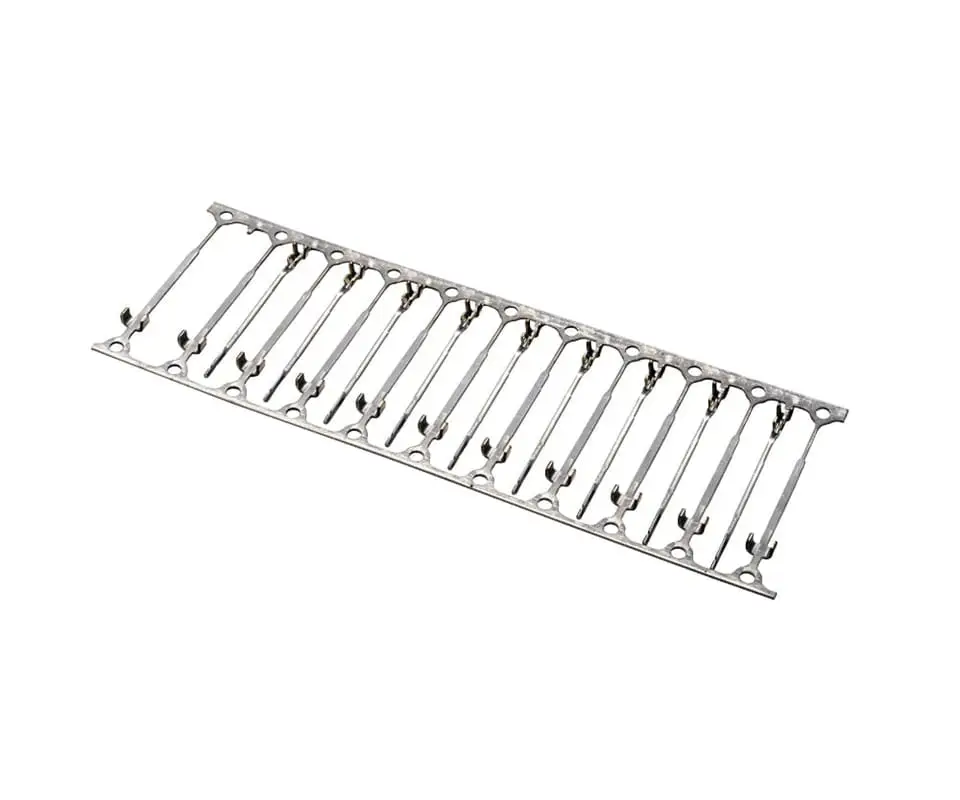
Every stamped electrical terminal decomposes into four functional zones, each with its own tolerance budget, material property requirement, and failure mode signature. A sourcing manager or design engineer who understands these zones can read a terminal drawing and identify the cost drivers and risk anchors without waiting for the supplier’s quote breakdown. The four zones —contact beam, retention lance, crimp barrel, and carrier strip —operate as a linked mechanical system where a tolerance drift in any single zone cascades into functional failure at the connector level.
The contact beam is the terminal’s heart. It is a cantilever spring that deflects under insertion to generate normal force against the mating pin or blade. Beam geometry —width, thickness, effective length, and preload angle —determines the contact normal force window.
A beam operating below the minimum normal force threshold develops fretting corrosion at the contact interface within 100 thermal cycles. Operating above the maximum threshold causes excessive insertion force and accelerates wear on the mating pin plating.
Kravzik models every contact beam in FEA before cutting tool steel, accounting for yield strength drift within the same temper designation —H02 phosphor bronze from one mill may deliver 480 MPa while another ships at 510 MPa, and the beam geometry must be robust across that 6% input variation.

The table below summarizes the core anatomical zones and their engineering boundaries for a typical automotive-grade terminal stamped from copper alloys:
| Anatomical Zone | Function | Typical Tolerance | Primary Failure Mode |
|---|---|---|---|
| Contact Beam | Generates normal force against mating pin; defines contact resistance at the interface | ±0.03 mm on beam width; ±0.05 mm on bend angle | Stress relaxation at elevated temperature; fretting corrosion under vibration |
| Retention Lance | Locks terminal into connector housing cavity; primary mechanical anchor against back-out | ±0.05 mm on lance height; ±0.03 mm on lance width | Lance breakage during extraction; undersized lance releasing after thermal cycling |
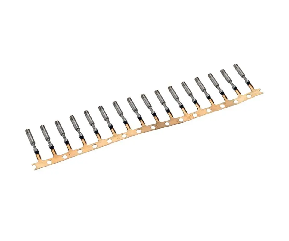
| Crimp Barrel | Wire termination zone; must cold-weld conductor strands under controlled compression | ±0.02 mm on barrel ID; ±0.05 mm on barrel height | Under-crimp causing high resistance; over-crimp fracturing conductor strands |
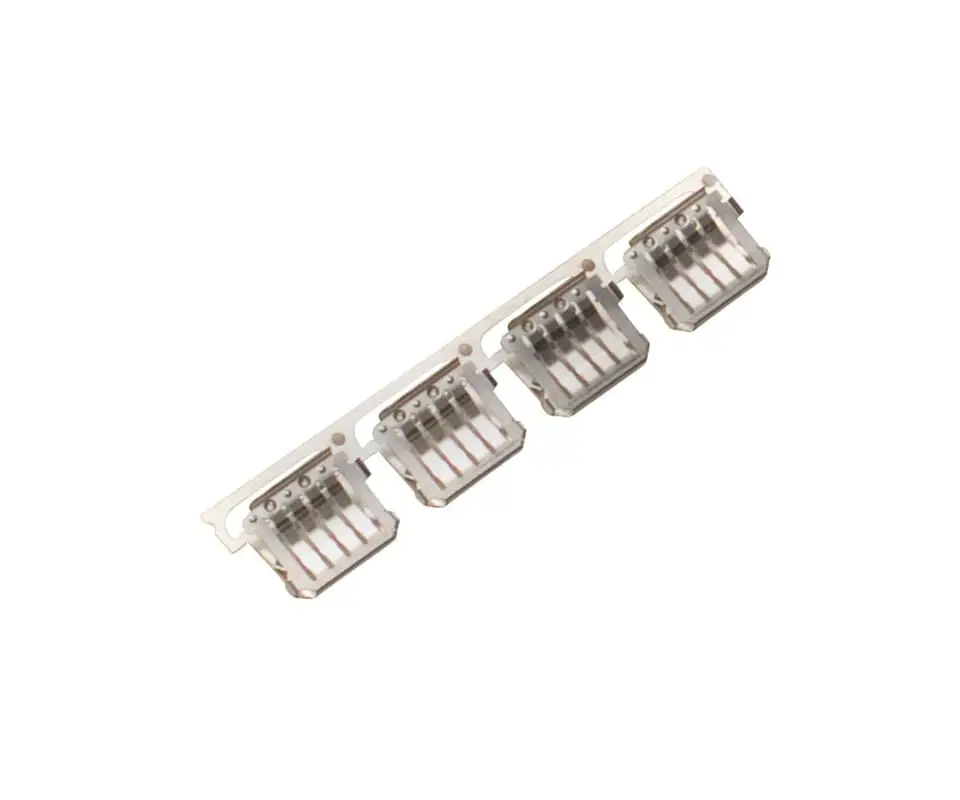
| Carrier Strip | Temporary web connecting terminals during stamping; cut off at connector assembly | Cutoff within 0.10 mm of body edge | Residual carrier protrusion causing dead-shorts against adjacent terminals |
The retention lance is frequently overlooked in early-stage design reviews —and it is the single most common root cause of terminal back-out failures in the field. A lance that is 0.03 mm undersized in height will hold during connector assembly but release under vibration after 500 hours of thermal cycling from –40 °C to +125 °C. Kravzik validates lance retention force on every new tool using a dedicated pull-test fixture that measures extraction force at both ambient and 125 °C, ensuring compliance with USCAR-2 pull-force requirements before the first production lot ships.
The crimp barrel governs the wire-to-terminal interface. In electrical stamping components, the barrel is typically an F-crimp or B-crimp geometry formed in the same progressive die that produces the contact beam. The barrel must be soft enough to deform around conductor strands without cracking, yet strong enough to maintain gas-tight compression through thermal cycling.
This dual requirement is why the temper specification for the base strip must balance formability at the crimp zone with spring properties at the contact beam —a tension that defines the entire material selection conversation and frequently drives the choice toward quarter-hard or half-hard tempers in phosphor bronze and brass alloys.
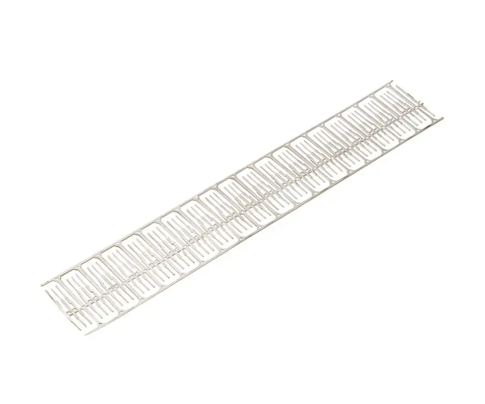
The Engineering Reality: Two terminals stamped from the same C51000 strip, at the same thickness, with the same plating stack, can differ in per-part cost by a factor of 2.5× based solely on secondary operations —selective plating start-stop precision, post-stamp heat treatment, and in-die staking of additional components.
Cost Drivers & Economics
The unit price of a stamped electrical terminal is dominated by three factors in descending order: material utilization, secondary operations, and tooling amortization. Understanding this hierarchy prevents sourcing managers from negotiating the wrong variable —squeezing the tooling supplier on die cost when 65% of the per-part cost lives in the strip layout and plating specification.
Material Utilization —The Number-One Cost Lever
Material cost alone represents 40% to 65% of the finished terminal price for copper alloys like phosphor bronze C51000 or beryllium copper C17200. The single most powerful cost lever is strip layout optimization —the geometric arrangement of the part profile within the carrier strip. A one-up die producing a 12 mm wide terminal on a 24 mm strip width discards 50% of the raw material as skeleton scrap.
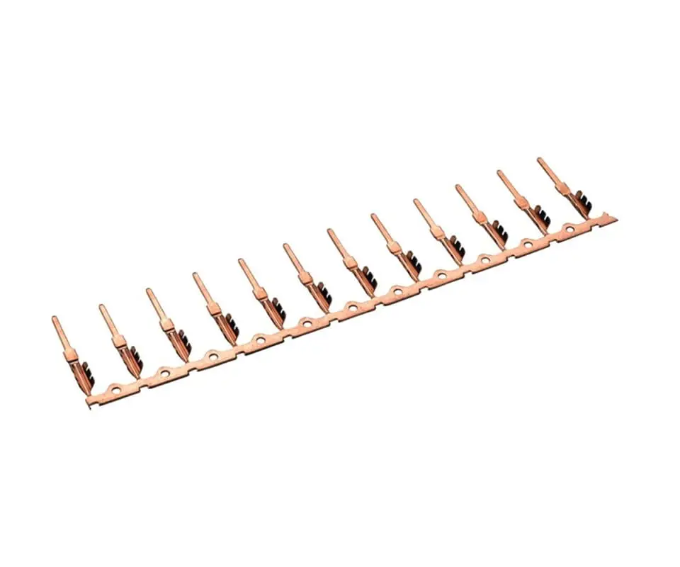
Moving to a two-up or three-up layout recovers 15% to 30% of that scrap, and the incremental tooling cost of adding cavities typically pays back within the first 200,000 pieces at current copper alloy pricing.
Kravzik‘s tooling engineers run strip layout simulations for every new terminal program, evaluating one-up through four-up configurations on a net-material-cost basis. A recent program for an EV busbar terminal moved from a two-up to a three-up progressive die —the added die cost of $8,500 recovered within three months at 500,000 pieces per year, and the customer’s per-part price dropped 19%. Decisions like this, made during the quoting phase before tool steel is cut, define the terminal’s cost trajectory for its entire production life.
Secondary Operations —The Hidden Multiplier
Secondary operations are the single largest source of cost variance between two terminals of identical strip thickness and base material. In electrical component metal stamping, the difference between a bare brass terminal and a selectively gold-plated contact beam terminal can be a 3× per-part cost multiplier. The operations stack up fast:
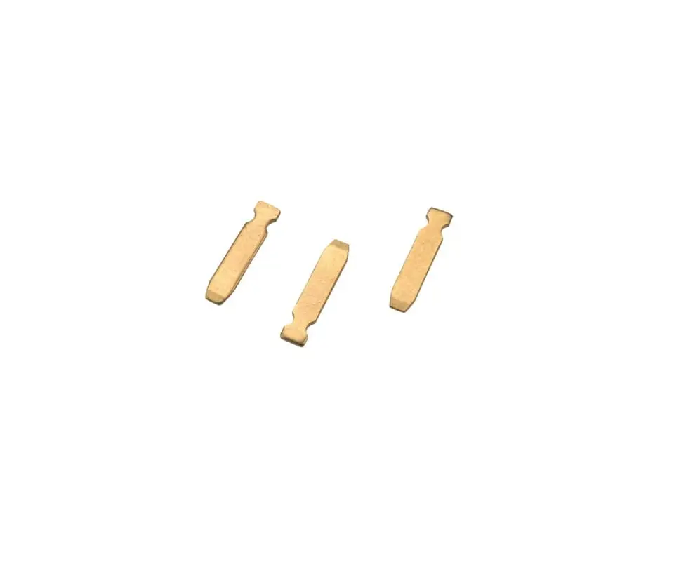
- Selective plating: Reel-to-reel selective gold over nickel on the contact zone alone adds $0.003 to $0.012 per terminal depending on spot size and gold thickness (0.38 µm to 0.76 µm). Overall plating wastes 70% or more precious metal on non-functional surfaces.
- Post-stamp heat treatment: Stress-relief annealing at 200 °C to 300 °C for 1 to 3 hours is mandatory for phosphor bronze terminals to restore formability after cold working. Skipping this step saves approximately $0.001 per part —and causes premature spring force relaxation within the first 1,000 thermal cycles.
- In-die staking: Integrating a secondary component —such as a stainless steel spring clip —into the terminal body during stamping eliminates a separate assembly station. The die becomes more complex, but the per-part assembly cost drops to near zero.
- Post-stamp cleaning: Alkaline degreasing followed by deionized water rinse is essential for removing stamping lubricants before tin plating. Contaminated surfaces cause plating adhesion failure —a defect invisible at outgoing inspection but catastrophic after 50 thermal cycles.
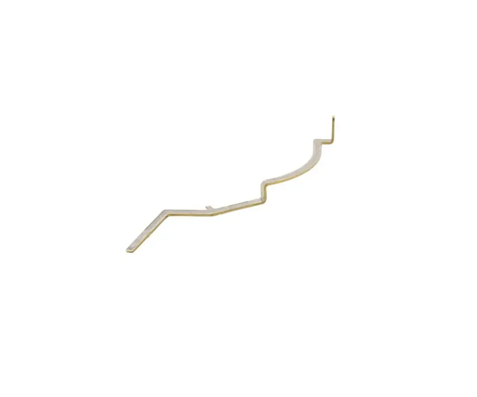
For buyers of custom metal terminals, the engineering takeaway is to request a cost breakdown that separates primary stamping, plating, heat treatment, and cleaning as individual line items. A supplier who quotes a single lump-sum price is obscuring the cost stack —and likely under-investing in the secondary operations that prevent latent field failures at 18 to 24 months.
Tooling Amortization —The One-Time Cost That Isn’t
A $35,000 progressive die spread over 500,000 annual parts adds $0.07 per unit in year one. By year three, when the die has produced 1.5 million parts, tooling contributes less than $0.025 per piece. The die typically lasts 5 to 10 million strokes before major refurbishment.
But this straight-line amortization model overlooks die maintenance cost: punch and die insert sharpening every 500,000 to 1 million strokes at $500 to $2,000 per event, plus the press downtime that pulls 4 to 8 hours from the production schedule. Kravzik builds progressive die tooling in-house using wire EDM, holding die clearances within ±0.0025 mm and extending tool life significantly compared to outsourced die construction with looser tolerance control.
💡 Cost Stack Analysis: request a line-item cost breakdown separating material utilization, secondary operations, and tooling amortization —so you negotiate the right variable instead of squeezing the wrong one.
Industry Scenarios
The same stamped electrical terminal process produces contacts for a $0.003 consumer USB connector and a $0.45 aerospace circular connector terminal. What changes between these extremes is not the fundamental stamping process. It is the specification envelope.
Understanding how each industry tightens different parameters prevents the most common sourcing error: applying automotive validation protocols to a consumer electronics program and destroying the cost model.
Automotive
Automotive stamped electrical terminals operate under the widest environmental envelope in the connector industry: –40 °C cold-start to 150 °C under-hood peak, with 1,000-hour thermal cycling and vibration profiles up to 20 G. The governing validation standard is USCAR-2 / LV214, which defines contact resistance stability, insertion-extraction durability (typically 10 to 25 cycles), and mixed flowing gas corrosion testing. Every terminal destined for automotive metal stamping programs must deliver PPAP Level 3 documentation with full dimensional layout, material certifications, and process capability studies demonstrating Cpk ≥1.67 on safety-critical dimensions and Cpk ≥1.33 on all other critical-to-function features.
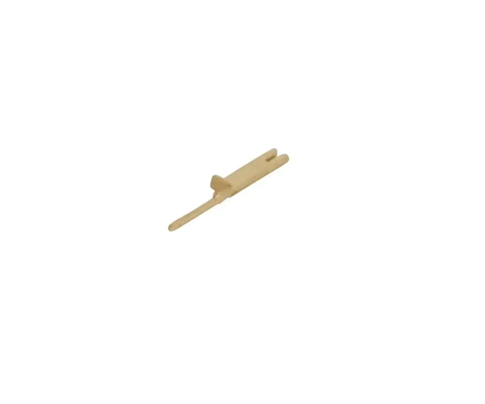
Kravzik‘s automotive terminal production runs on Bruderer high-speed presses with real-time SPC monitoring at 20-minute sampling intervals. Critical dimensions —contact beam width, lance height, crimp barrel gap —feed directly into a live Cpk dashboard that flags any dimension approaching the 1.33 alert limit before it produces a single non-conforming part.
Medical Devices
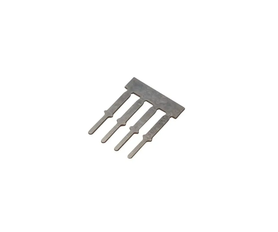
Medical stamped electrical contacts for diagnostic equipment, patient monitoring, and surgical instruments impose unique material constraints: the terminal must survive repeated autoclave sterilization at 134 °C saturated steam, or chemical sterilization with hydrogen peroxide plasma, without corrosion or spring force degradation. This eliminates standard tin plating —which oxidizes rapidly under steam exposure —and shifts the plating specification toward 1.27 µm minimum gold over palladium-nickel. Biocompatibility per ISO 10993 is mandatory for any terminal that contacts the patient or fluid path.
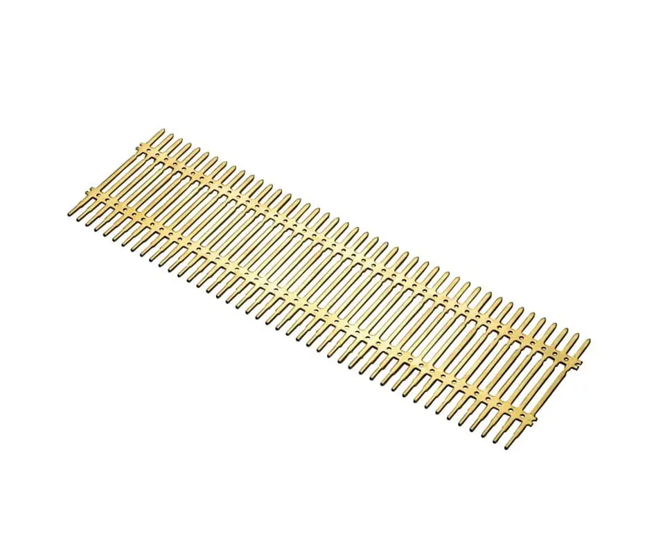
Kravzik maintains a dedicated medical-grade production cell with full lot traceability from coil certificate to finished terminal reel. Each lot ships with a complete material cert package including alloy chemistry, temper verification, plating thickness XRF report, and sterilization cycle validation data. This level of quality management system documentation is table stakes for medical device stamping —not a value-add.
Industrial Automation & Power Distribution
Industrial power terminals for motor drives, PLC I/O modules, and DIN-rail connectors operate at 10 A to 75 A continuous with occasional surge currents exceeding 150 A. These electrical stamping parts use thicker stock —0.40 mm to 0.80 mm in high-copper alloys —and require larger contact normal forces of 5 N to 15 N. The predominant failure mode shifts from fretting corrosion (dominant at signal levels) to thermal runaway at the contact interface, driven by I²R heating at the constriction resistance points where mating surfaces make actual contact.
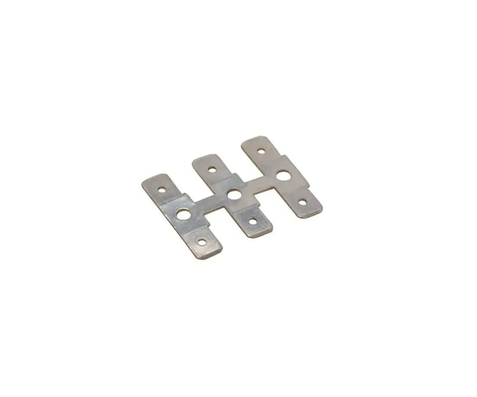
Kravzik subjects power terminals to 100% contact resistance testing on automated reel-to-reel systems that measure voltage drop at rated current. Terminals falling outside the ±15% window are mechanically ejected from the reel before shipment —a closed-loop gate ensuring no single high-resistance terminal reaches the customer’s automated connector assembly line.
Consumer Electronics
Consumer electronics stamped electrical terminals for USB-C, battery contacts, and FPC connectors push toward the thin end of the material spectrum —0.10 mm to 0.25 mm stock processed at 800 to 1,200 SPM. The cost pressure is extreme: a $0.001 per-part difference across 50 million annual units translates to $50,000.
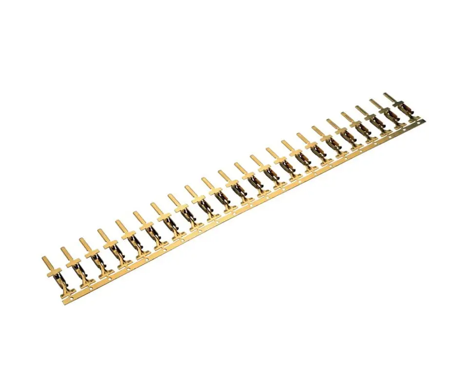
Material utilization becomes the overriding variable, and strip layouts routinely push to four-up configurations with ultra-narrow skeleton webs below 1.5 mm. Kravzik‘s high-speed lines for consumer terminal production prioritize strip utilization above 85% through multi-row nesting and shared carrier strip designs that minimize the material cost component of the finished terminal price.
Quality Standards & Validation
Stamped electrical terminals are not commodity fasteners. A terminal carries both mechanical and electrical function simultaneously, and the validation regime must verify both domains across the full environmental envelope. Skipping any test tier —dimensional, mechanical, electrical, environmental —creates a blind spot that reliably produces field failures at approximately 18 to 24 months of service life.
Dimensional Validation
First Article Inspection per AS9102 or PPAP Level 3 requires 100% dimensional layout on a minimum sample of 5 pieces per cavity. Kravzik uses Keyence optical measurement systems capturing 300+ dimensions in under 3 seconds per terminal, generating a full dimensional report with deviation from nominal for every critical-to-function feature. The report includes Cpk calculations for the production run from which the FAI samples were drawn.
Mechanical & Electrical Validation
Insertion force, extraction force, and normal force —measured at both ambient and temperature extremes —form the mechanical validation triangle. The core electrical test is Low Level Contact Resistance (LLCR) per EIA-364-23, measured at 20 mV open-circuit and 100 mA maximum to avoid fritting through oxide films.
The pass criterion for automotive-grade terminals is 10 mΩ initial and 15 mΩ after environmental exposure. Environmental testing follows a sequenced profile: thermal shock (-40 °C to +125 °C, 100 cycles), mixed flowing gas (48-hour Cl₂ + H₂S + NO₂), and humidity-temperature cycling (40 °C / 95% RH, 500 hours).
For IATF 16949-governed programs, Kravzik submits full PPAP documentation including PFMEA, Control Plan, MSA studies on all measurement systems, and capability studies demonstrating Cpk ≥1.67 on all SC and CC dimensions. This closed-loop documentation workflow is embedded in Kravzik‘s quality management system, ensuring every lot ships with a complete, auditable cert package.
Risk Anchors & Latent Failure Modes
Stamped terminal failures share a common signature: they are latent. The terminal passes outgoing inspection, passes the customer’s incoming QC, and functions correctly through the connector assembly process. The failure emerges 6 to 24 months into field service, triggered by thermal cycling, vibration, or environmental exposure.
Understanding these failure modes at the sourcing stage —before tool steel is cut —is the most reliable defense against latent field returns.
Burr-Induced Contact Resistance
A 50 µm burr on a contact beam edge is invisible without magnification but creates a localized contact pressure point that concentrates the entire normal force onto a 0.05 mm² area. The result is a contact resistance spike from 5 mΩ to 50 mΩ or higher —and when that terminal carries 15 A continuous, the I²R heating at the burr tip raises the local temperature by 40 °C above ambient.
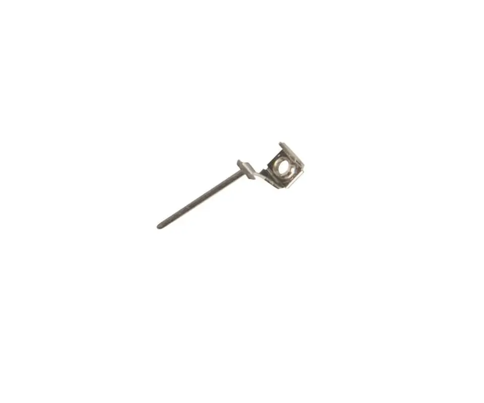
This accelerates oxidation, further increases resistance, and eventually triggers thermal runaway. Kravzik maintains progressive die tooling punch-to-die clearances at 5% to 8% of material thickness and resharps cutting elements on a stroke-count schedule —not a visual-inspection schedule —to keep burr height below 25 µm across the full production run.
Hydrogen Embrittlement After Plating
Electroplating operations —particularly nickel and gold and silver plating —introduce atomic hydrogen into the metal lattice. If the terminal is not baked within 4 hours of plating at 190 °C to 210 °C for 3 to 8 hours per ASTM B850, the hydrogen migrates to stress concentration points —bend radii, lance roots, crimp barrel transitions —and initiates intergranular cracking.
A terminal that bends 90° in a forming die will crack at a 45° bend after hydrogen embrittlement takes hold. The post-plating bake is the single most commonly skipped process step in low-cost terminal supply chains, and the failure it produces is invisible until the terminal fractures under mechanical load in the field.
Fatigue Cracking at Tight Bend Radii
Every bend in a stamped terminal creates residual tensile stress on the outer radius. When the bend radius-to-thickness ratio drops below 1.0, the outer fiber strain exceeds the material’s uniform elongation limit.
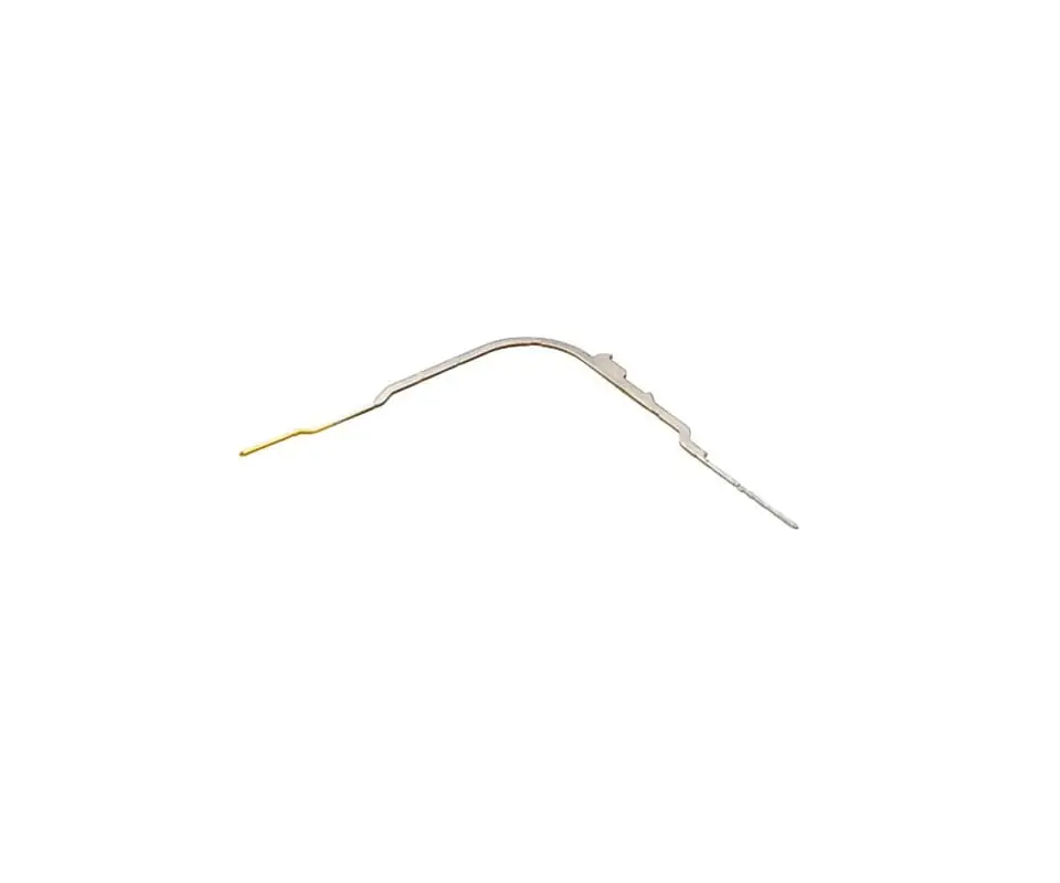
This does not cause immediate cracking —the terminal forms successfully in the die —but it creates a nucleation site that propagates under cyclic mechanical load. Kravzik enforces R/t ≥1.0 on all forming bends in electrical stamping components and uses FEA to verify that the maximum principal strain after springback does not exceed the material’s elongation at break minus a 15% safety margin.
Plating Thickness Variance on Formed Surfaces
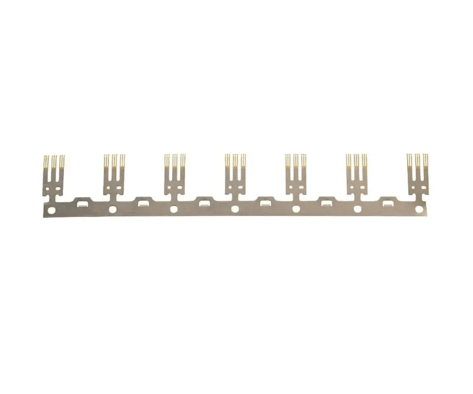
Reel-to-reel selective plating deposits a uniform coating thickness on flat strip. But after forming, the plating thins on convex surfaces and thickens on concave surfaces. A 0.76 µm gold spot on the flat strip can thin to 0.30 µm on the outer radius of a formed contact beam.
Below 0.38 µm gold, porosity increases exponentially, and the underlying nickel is exposed to the operating environment.
For custom metal terminals with complex 3D formed geometries, Kravzik specifies plating thickness at the formed surface —not the flat strip —and validates with cross-sectional SEM on first-article samples from every cavity.
Your Action Roadmap
Burr excursions detected at assembly expose supplier SPC gaps that surface only after 500,000 strokes. Kravzik’s progressive die tooling and digital strip simulation close this gap before tool steel is cut, with Cpk monitoring and full material traceability delivered as standard practice.
Describe your terminal application for a comprehensive feasibility assessment with tooling strategy and transparent cost data. Kravzik returns a production roadmap within 48 hours, under strict NDA.